Projects#
Delving into geometry nodes may appear daunting, but you will be able to create all kinds of stunning effects once you get the hang of it. Here are some examples to get you started.
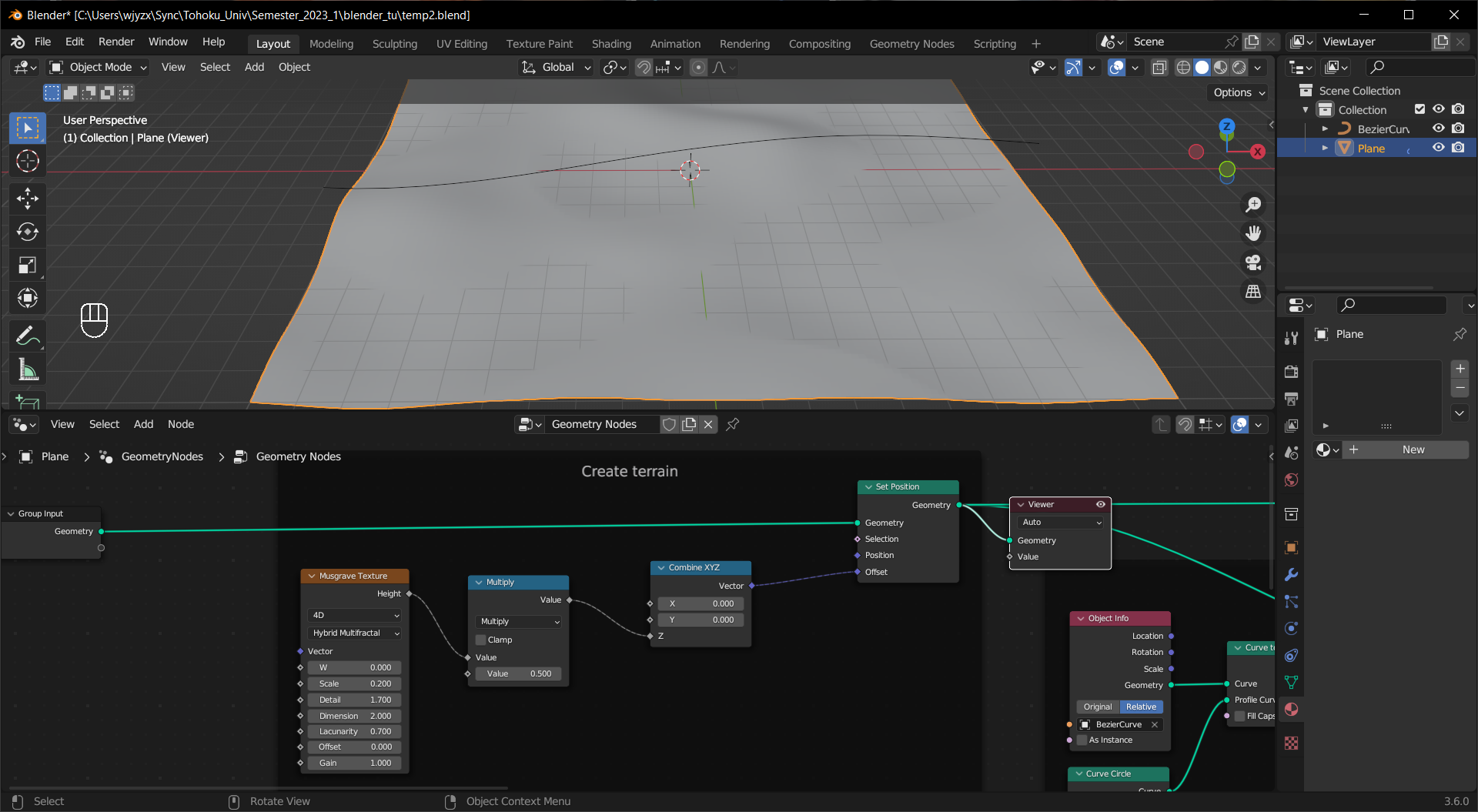
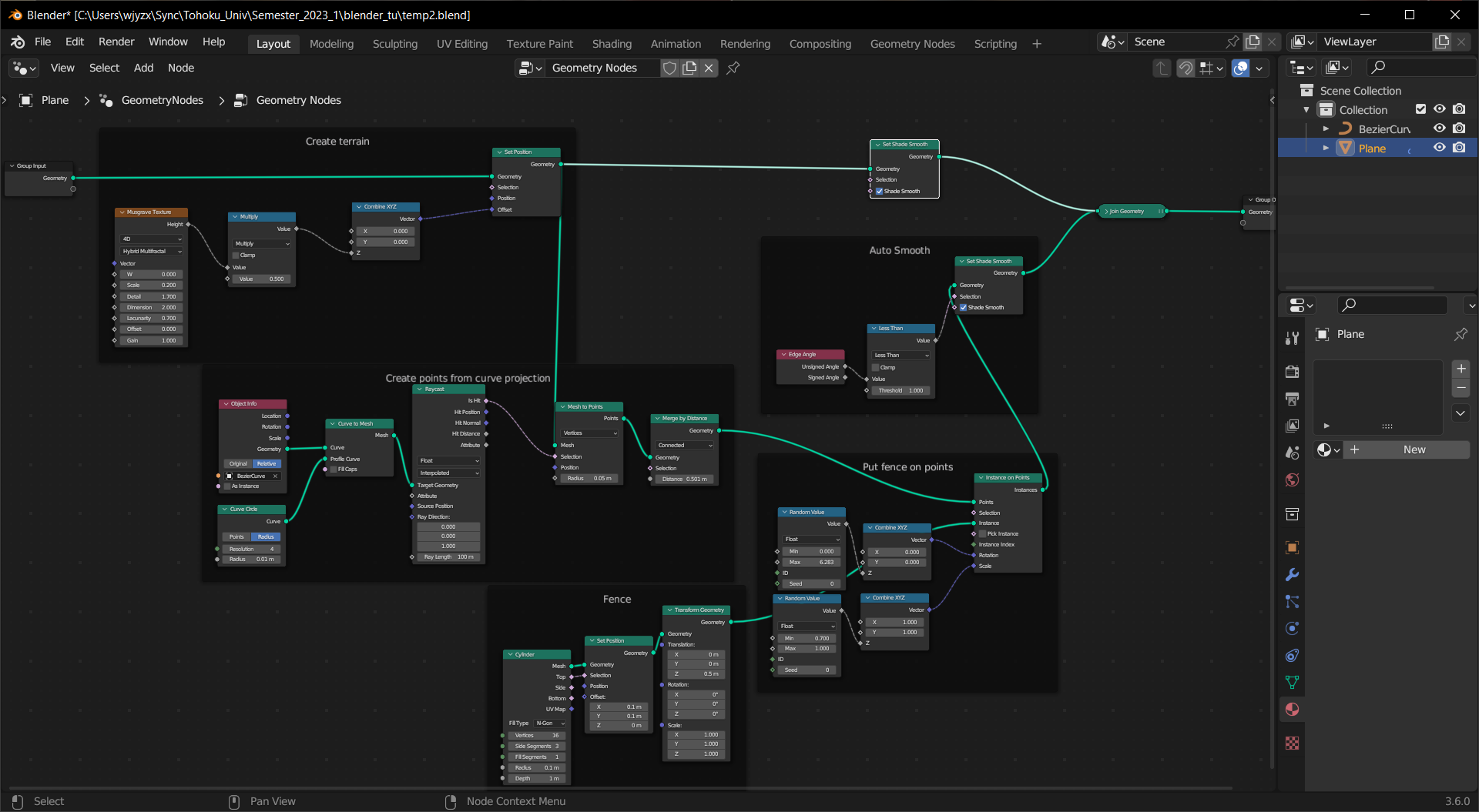
This node tree creates an uneven terrain and puts down fences below a curve object.
To create the terrain, a Musgrave Texture is used to adjust the locations of the vertices on the Z axis. Like Displacement in shaders, the input plane needs to have enough vertices to make it happen.
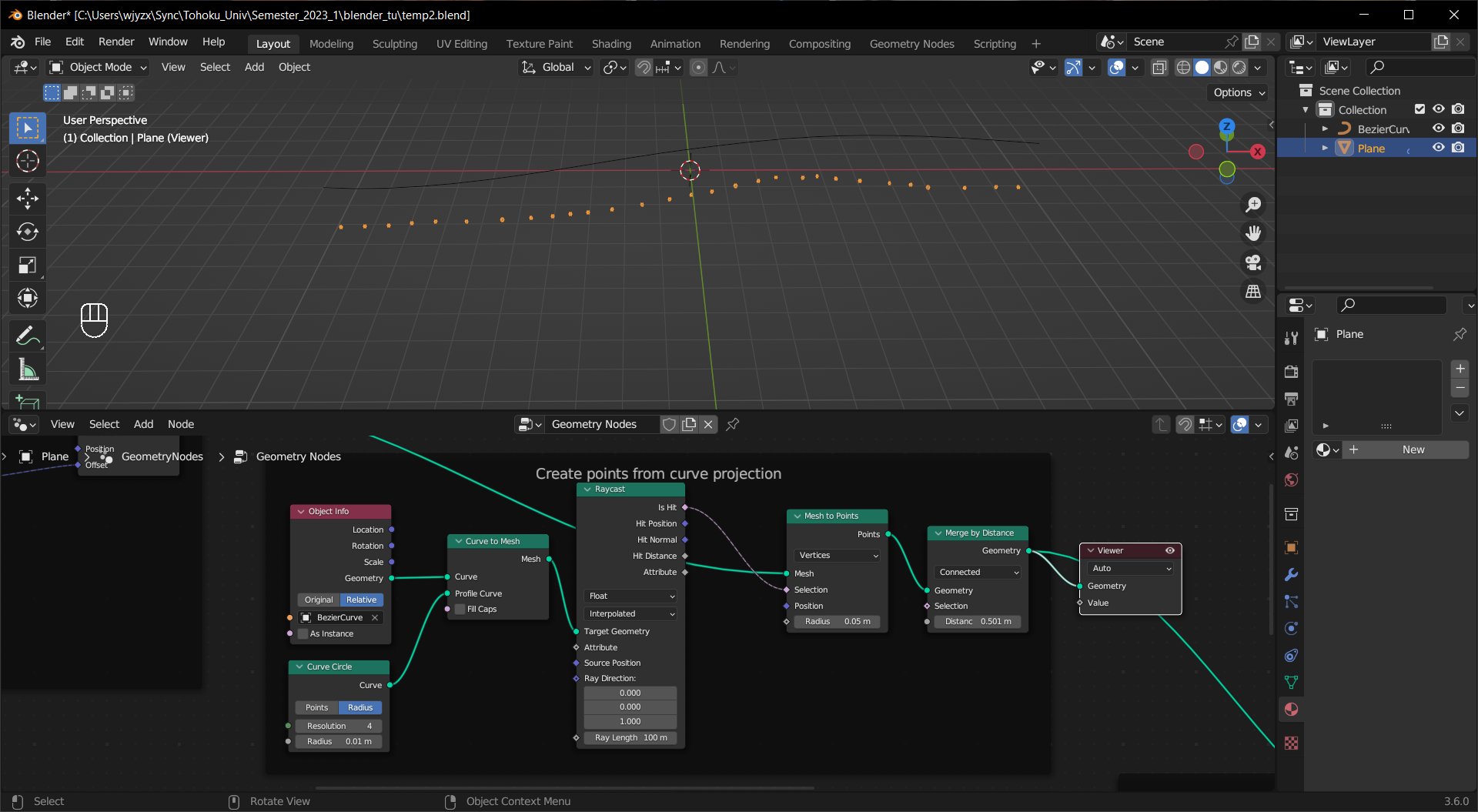
An Object Info node is used to retrieve the information from the curve object, and by giving it a profile we are able to determine the points below the curve with the Raycast node. The Merge by Distance node controls the number of points.
Tip
Linking the Object input socket of the Object Info node to the Group Input node will make it possible to choose the curve object in the Geometry nodes modifier.
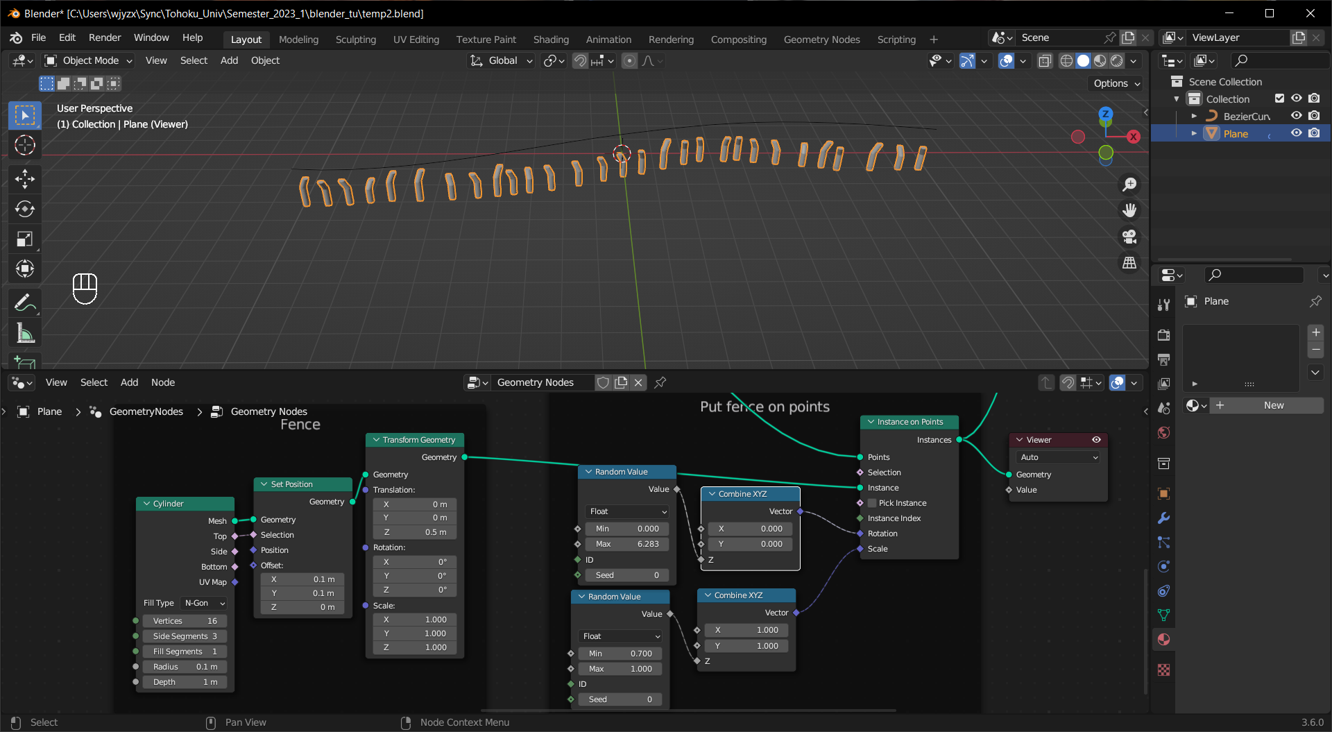
The fences are made of cylinders with twisted tops and put on the points with random scale and rotation.
Tip
You can make the fences manually and replace the nodes in the “Fence” frame with an Object Info node.
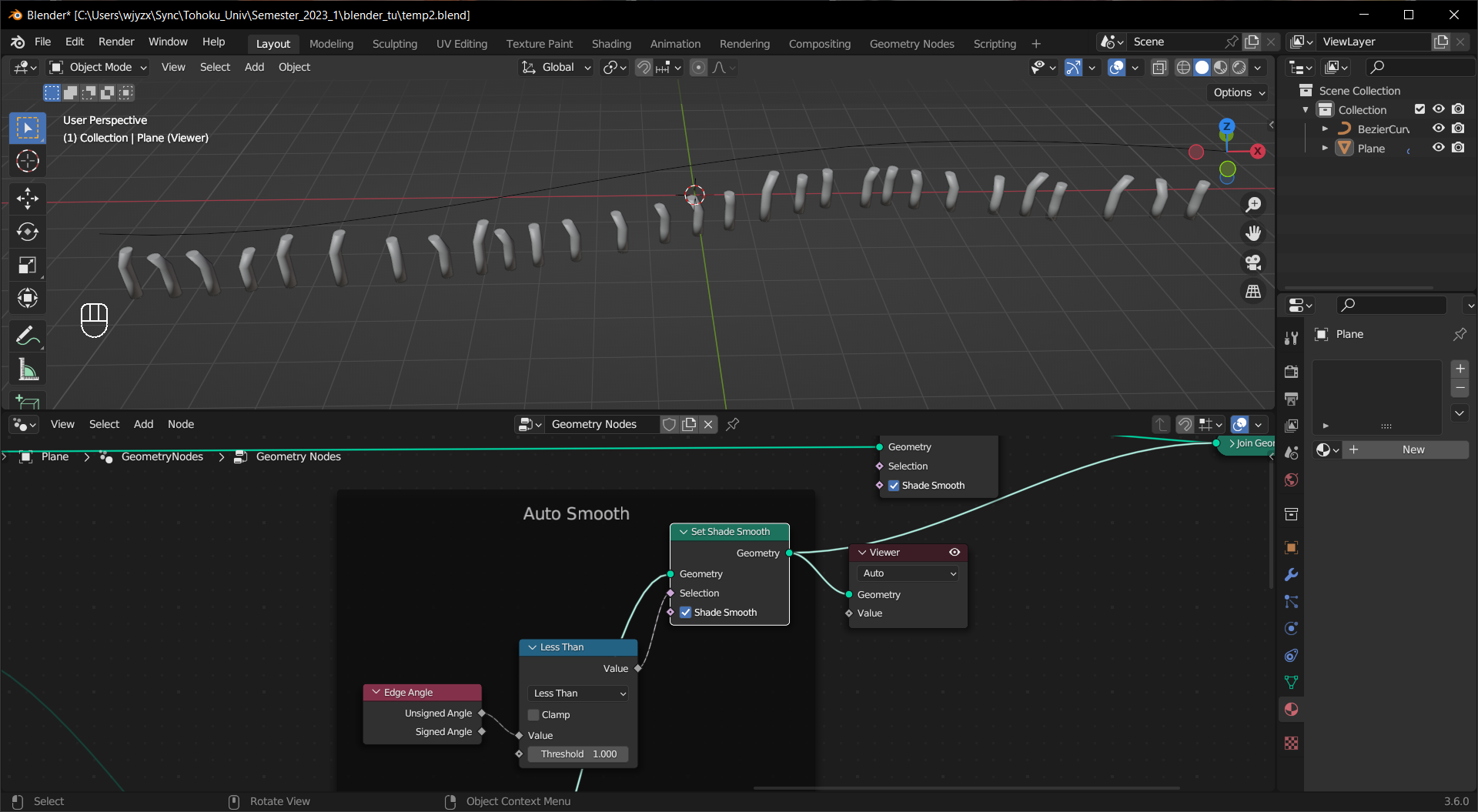
There is no shade auto smooth node in geometry nodes but you can achieve the same effect by selecting the faces to shade smooth with Edge Angle node.
Combining all the parts and we have the whole node tree.
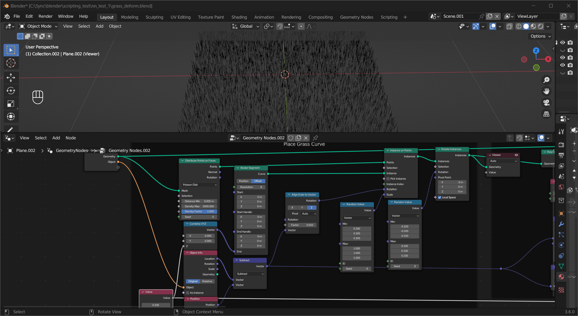
This geometry node tree creates grass-like instances on a plane and deforms them based on their distance from another object.
A straightened Bezier Segment is used to represent a grass blade, and its instances are randomly distributed on the plane. A Random Value node connected to the Scale input socket of the Instance on Points node gives the grass some size variation, and the vector pointing from each instance to the object location is calculated to rotate the grass blades to face the object with the help of the Align Euler to Vector node. An additional Rotate Instances node adds slight random rotation to the instances, helping them to look more natural.
Tip
You need to give the curves a profile to see their facing.
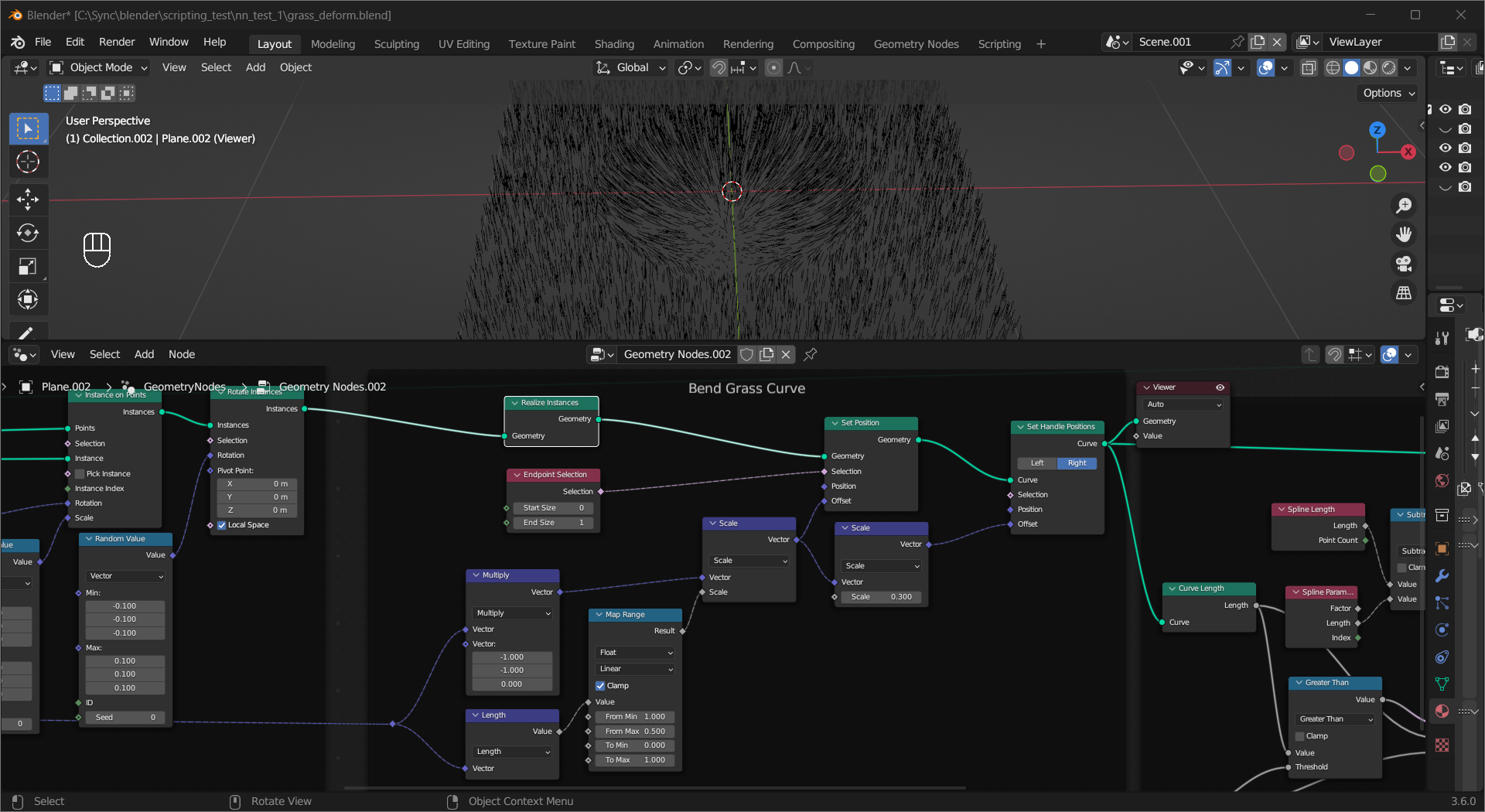
To bend the grass blades in different directions, first we need to use Realize Instances to give them real geometry. Reuse the vector calculated in the last frame to move the control points, also adjust the handles to make a nice curve.
Tip
The blue diamond reroute is connected to the
Vectoroutput socket of the Vector Math(Subtract) node in the previous frame.For simplicity, This approach actually stretches the grass blades.
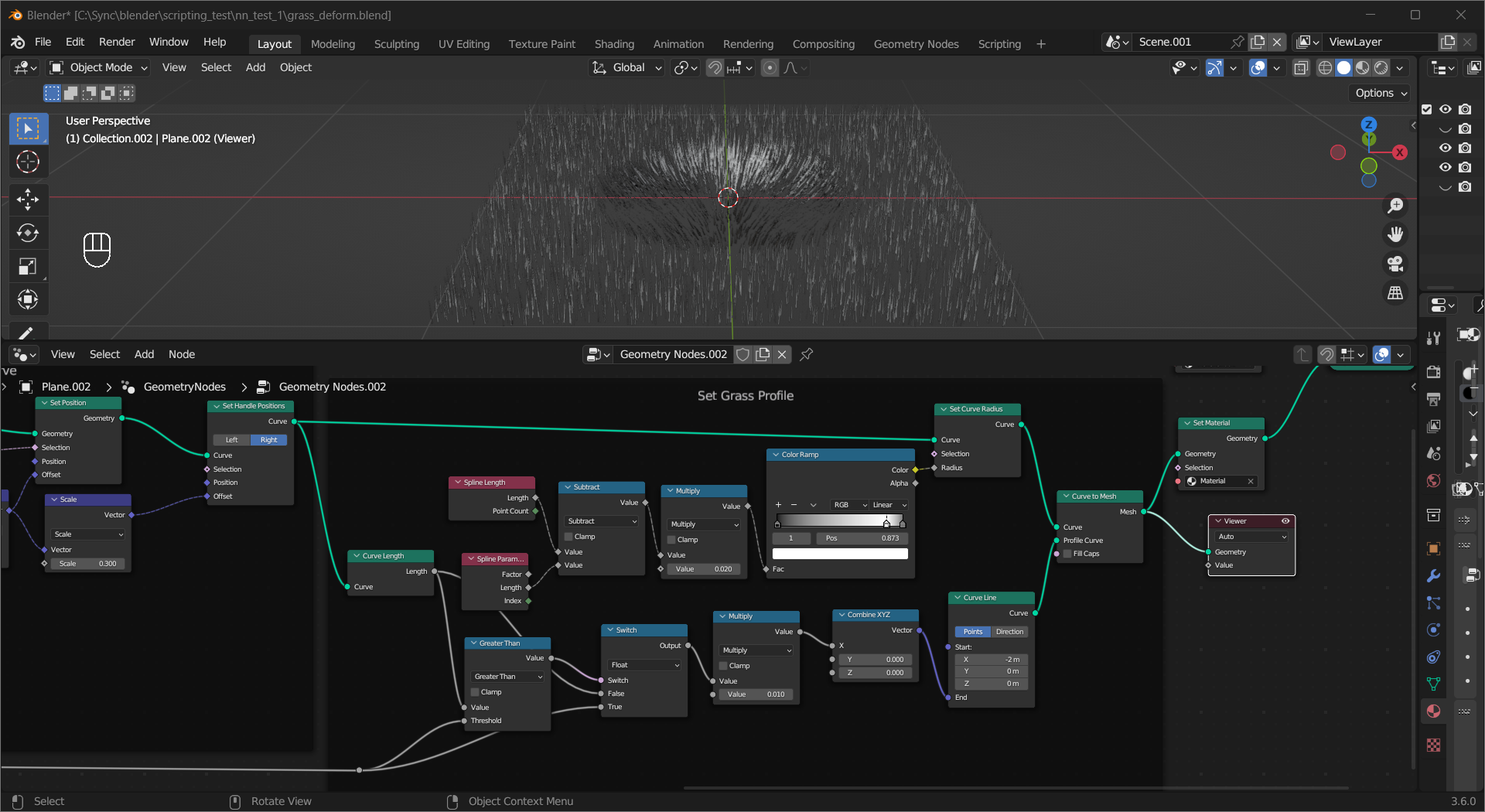
Add a profile curve to finalize the look. The Curve Line node is used to make the profile curve, and its length is proportional to the length of the grass. The taper of the grass blades is calculated based on the difference between the length of the curve(Spline Length node) and the distance to each control point (Length output of the Spline Parameter node), with some adjustments.
Tip
The grey reroute is connected to the Value node in the first frame.
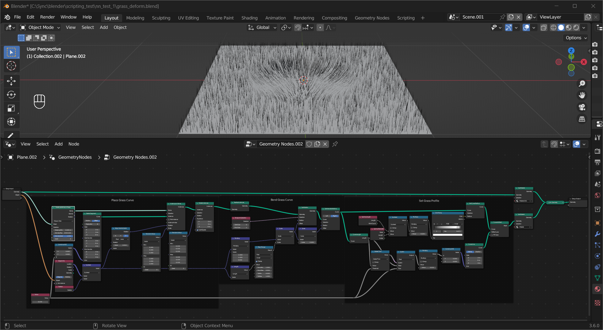
Adding material (diffuse color only in this example) and combining the ground and grass with Set Material and Join Geometry nodes gives the final result. Add a camera pointing at the plane and save this project and you can use it in the next chapter.
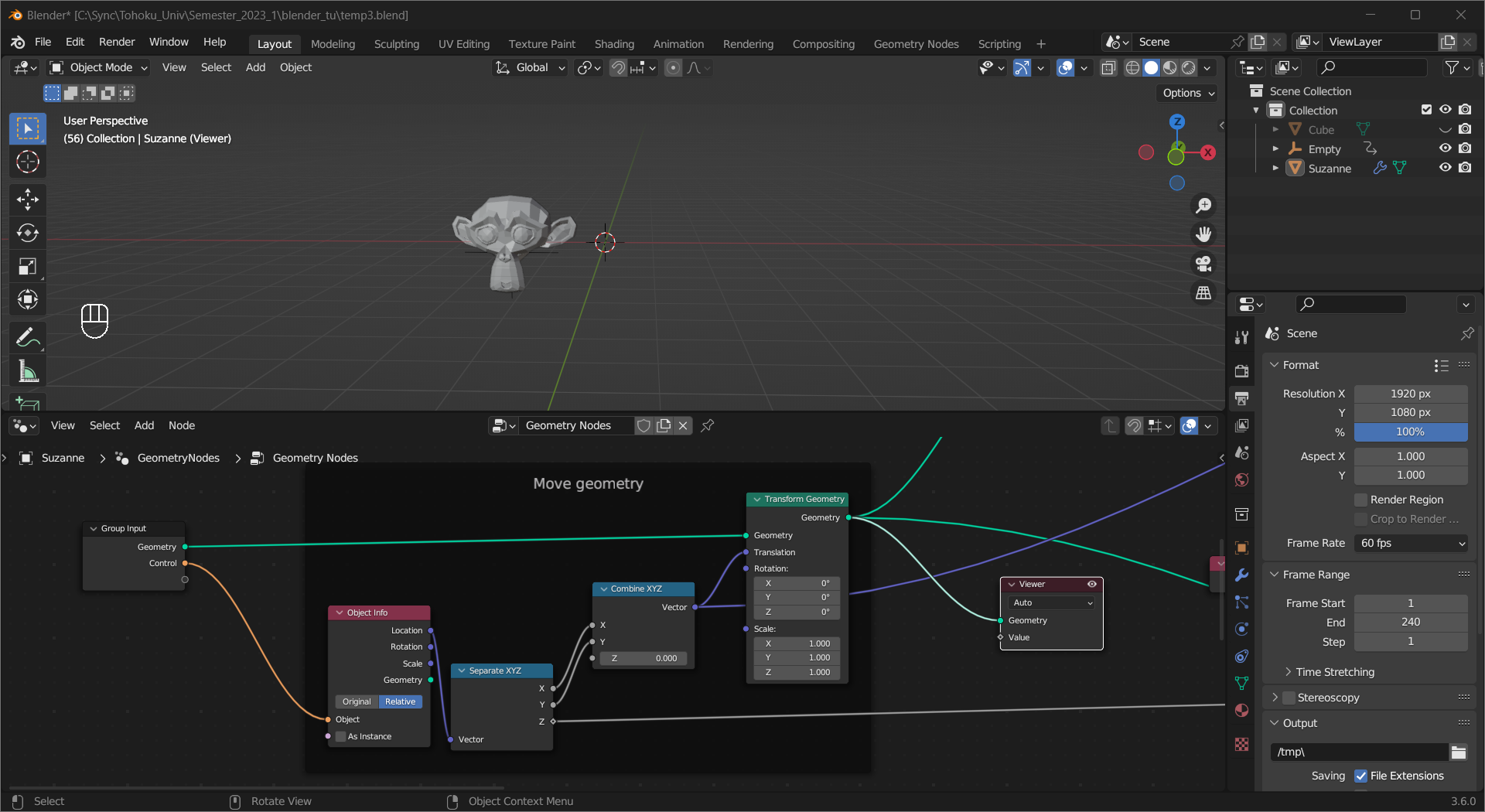
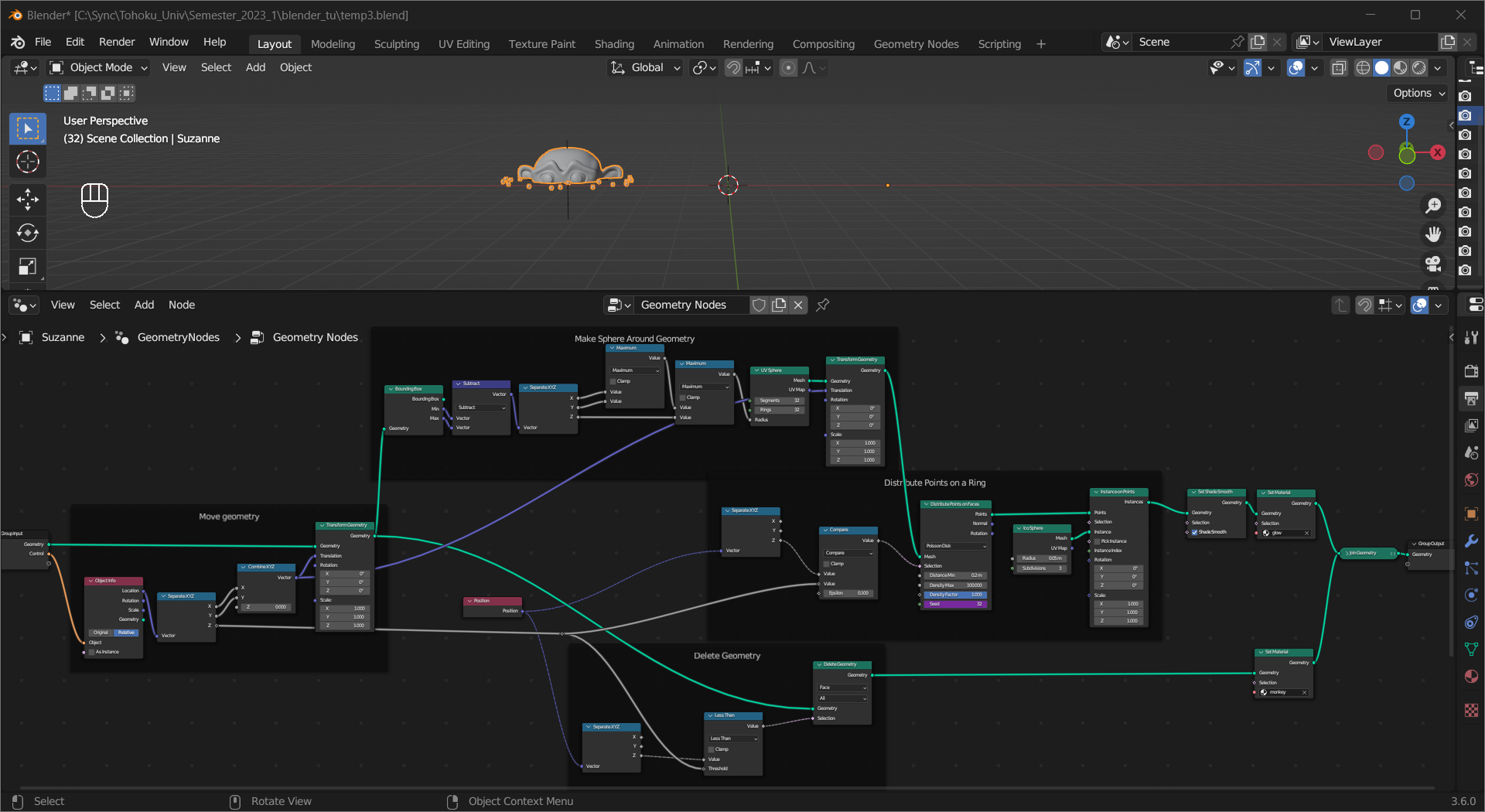
This node tree creates a teleportation effect.
First we make the source object follow the movement of the control object on the X and Y axes using the Transform Geometry node. To get the location of the control object, an Object Info node is added.
Tip
The Z axis of the object is set to 0, but since it is the local axis you can still move the object up and down without breaking the effect.
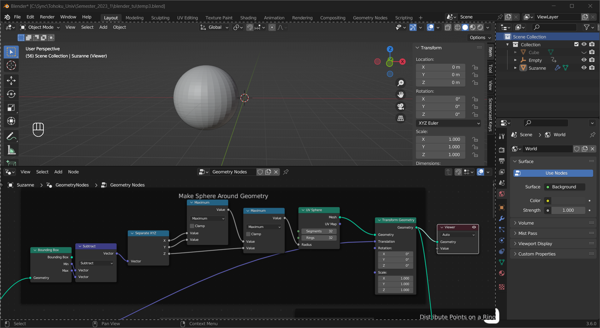
To create the particle ring effect around the object, we first create a sphere enveloping the source object. The Bounding Box node is used to calculate the radius of the UV sphere, and the sphere is moved to the same location as the source object.
Tip
The Translation input of the Transform Geometry node here is the same as the one above.
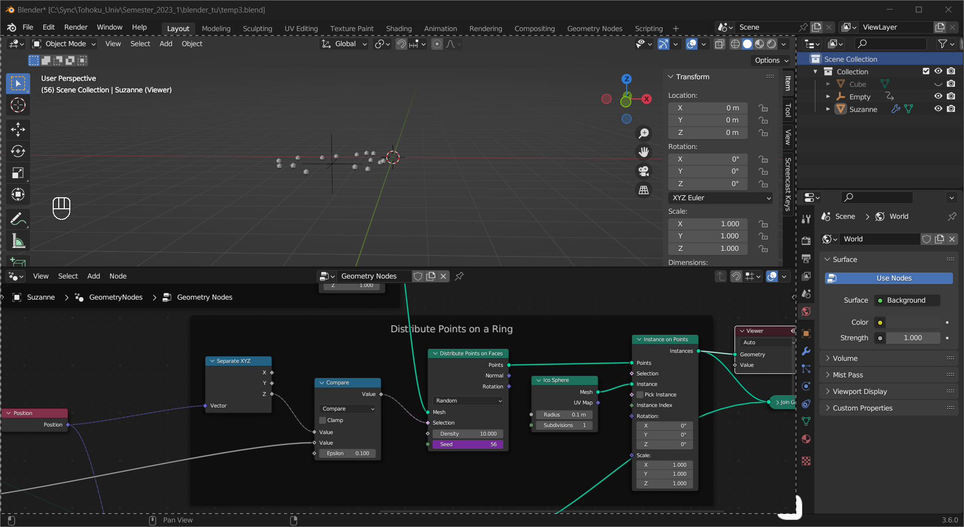
The points are generated on the surface of the sphere where the Z coordinates are close to the one of the control object. Instances of an ico sphere are used to represent the particle effect.
Tip
The second input of the Math(Compare) node is the Z location of the control object.
The
Seedof the Distribute Points on Faces node has a driver(#frame) to shuffle the points every frame.
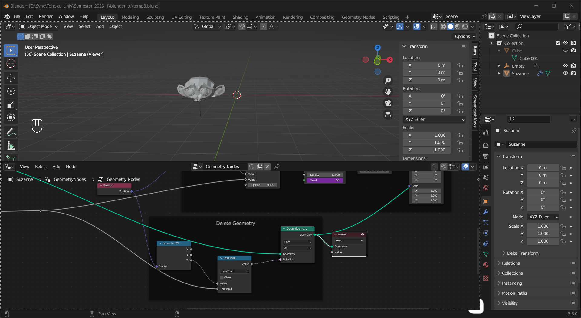
To “teleport” the source object, use a Delete Geometry node to delete all geometry below the Z location of the control object.
Tip
The Threshold input of the Math(Less Than) node is the Z location of the control object.
Combine the geometry and the instances, give the control object some simple animation, and we have the result.
Feel free to tune the parameters and add materials to it.
Tip
The glow is added in Compositing.