Geometry Node Basics#
If you have already mastered shader nodes, then you get yourself a head start in Geometry Nodes. Node-related operations, such as adding, linking, and arranging nodes, stay the same, refer to that chapter when you want a refresher.
Adding Geometry Nodes to Objects#
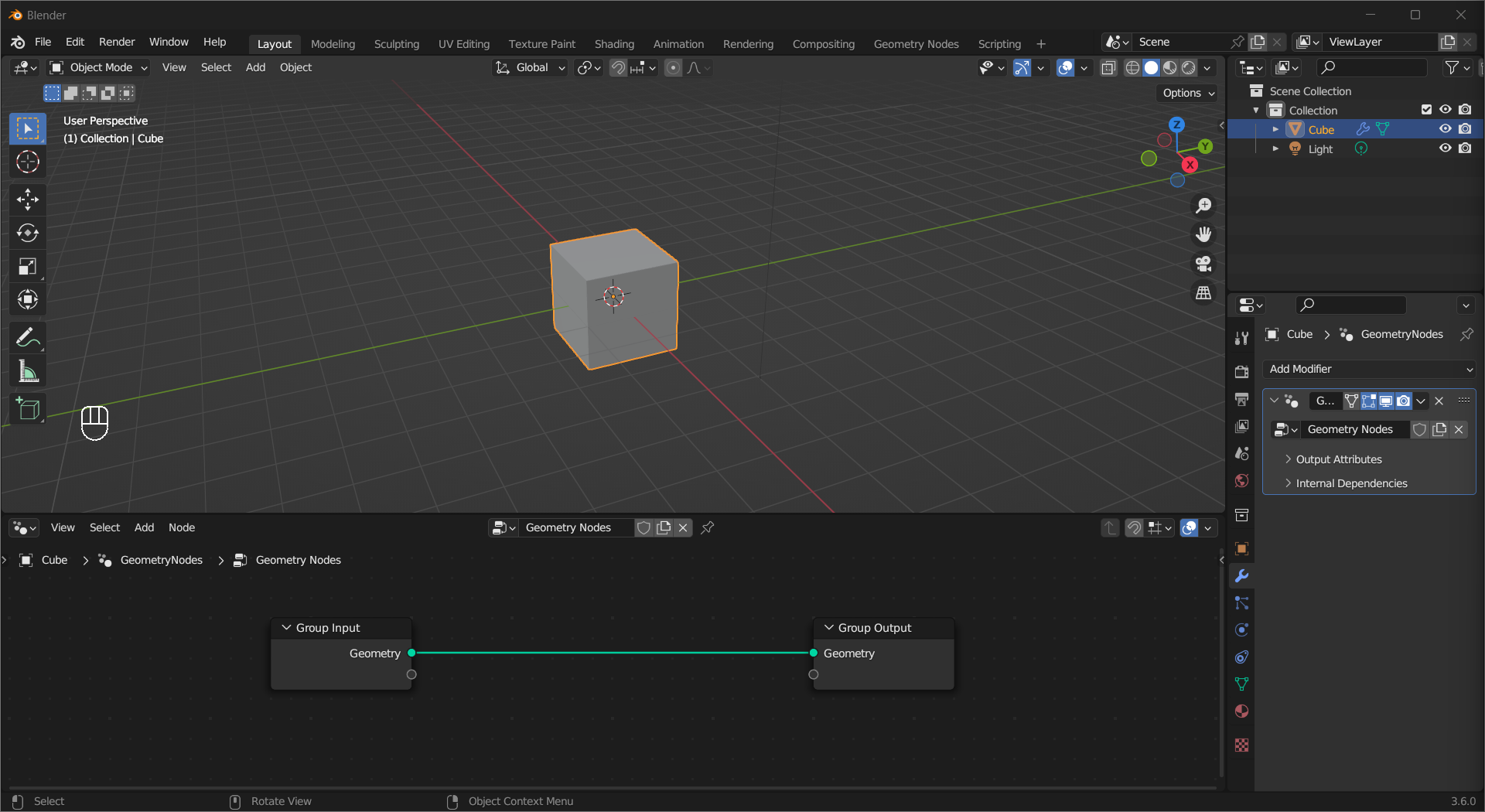
To make geometry nodes work, an object needs a Geometry Nodes modifier linked to a Geometry Node Group node tree. To start from scratch, select the object, then Left Mouse Click New on the header of a Geometry Node Editor area. If you want to use an existing node tree, add a Geometry Nodes modifier then Left Mouse Click the icon to the left of the New button and select the node tree.
Tip
You can switch to the Geometry Nodes workspace to access the areas.
Like any other modifiers, you can control its visibility, and how it interacts with other modifiers.
The default node tree has a Group Input and a Group Output node. The former is optional, you do not need it if your node tree does not use the original geometry and requires no input attributes.
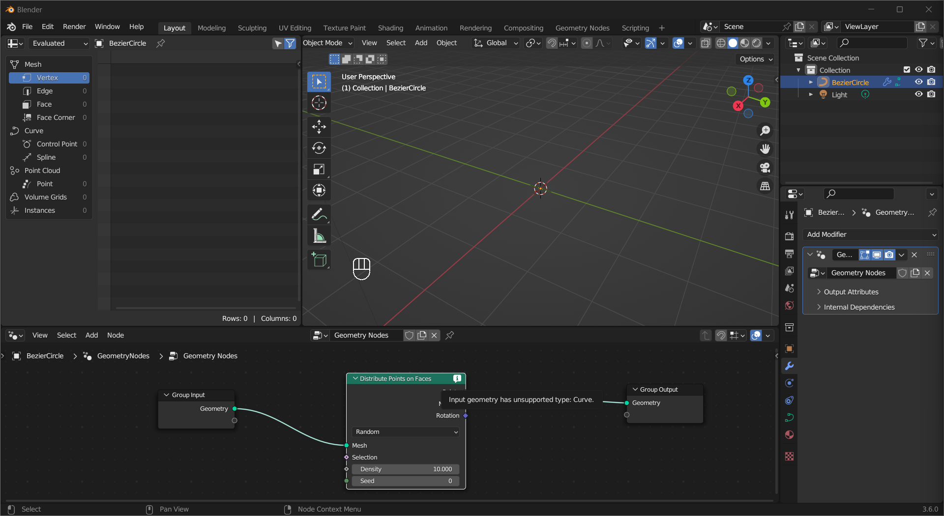
If all connected sockets are compatible but a node gets unsupported input, it will have a warning on its top right corner.
Points and Instances#
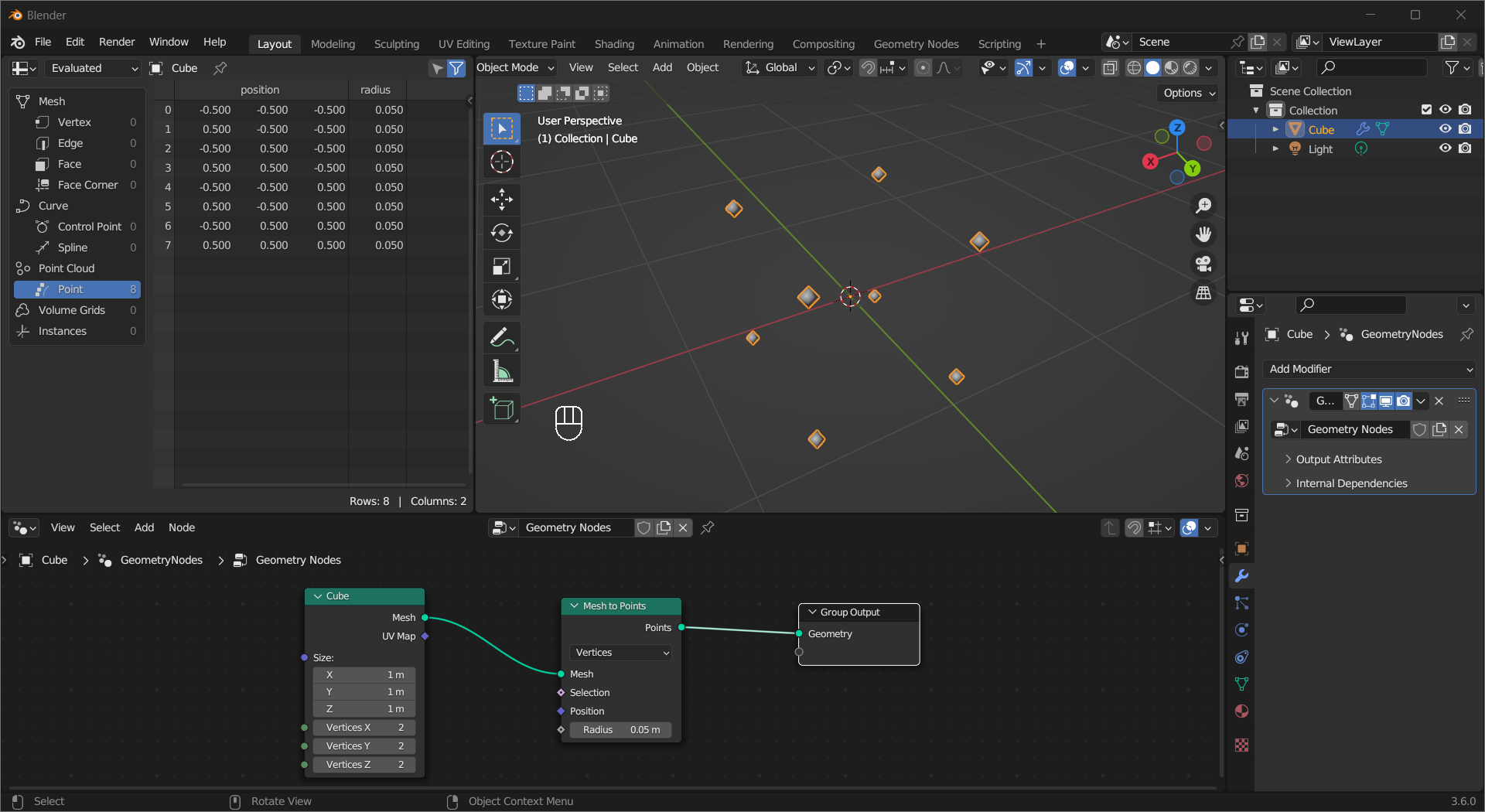
Points and Instances are two concepts you will encounter a lot when building a node tree. A point, as its name suggests, is a point in space represented by a diamond in the viewport. To get the exact information, make a new area and switch it to Spreadsheet. If you connect a Geometry/Mesh/Curve output to a Points socket, vertices/control points will be interpreted as points. The Mesh to Points/Curve to Points node gives you more control over this transition.
Tip
The diamonds may look like meshes but they do not really exist, try to render it and you will find out.
The
Spreadsheetarea provides valuable information for building node tree, sadly it may not always be shown in the screenshots due to limited screen estate.
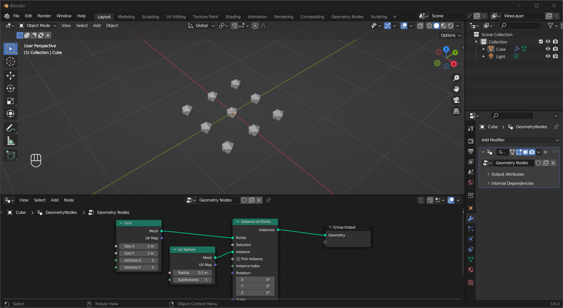
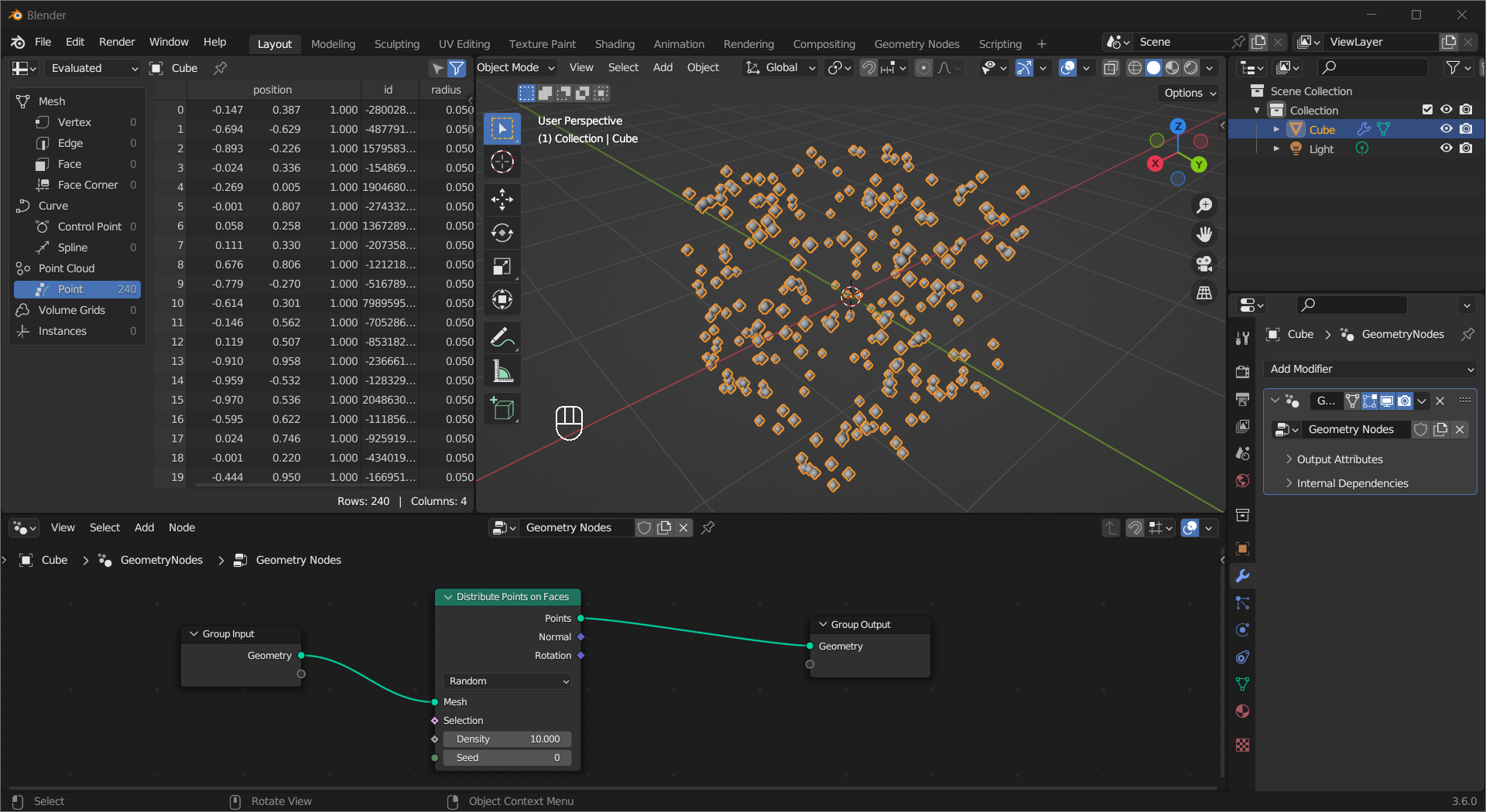
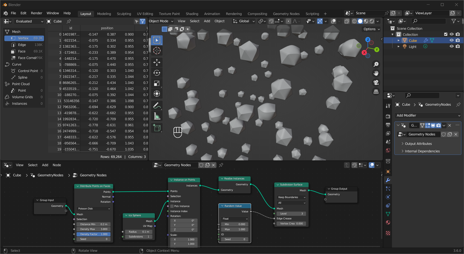
A common way to use points is to randomly generate them on the surface of a mesh using the Distribute Points on Faces node.
Tip
The Poisson Disk option is useful if you want to limit how close two points can get.
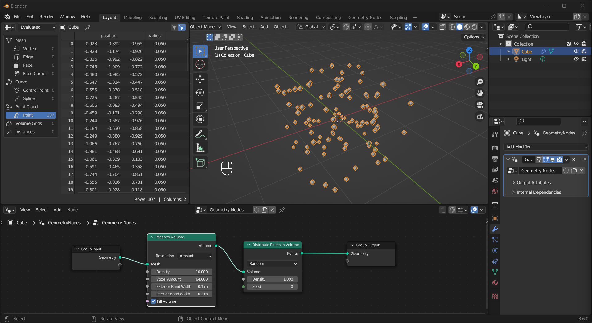
Or inside the mesh using a combination of the Mesh to Volume and Distribute Points in Volume node.
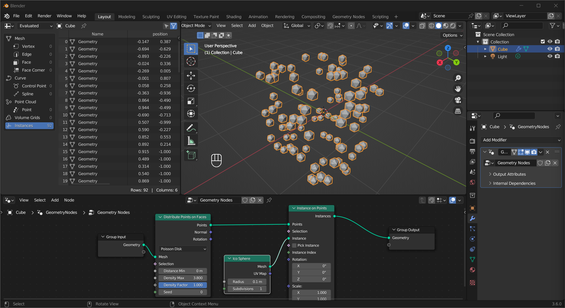
Once you got some points, you can put instances, which are like linked copies of an object, at their location using the Instance on Points node.
To make changes to individual instances, you need to make them have their own geometry data using the Realize Instances node. This example applies Subdivision Surface to all meshes with randomized Edge Crease values.
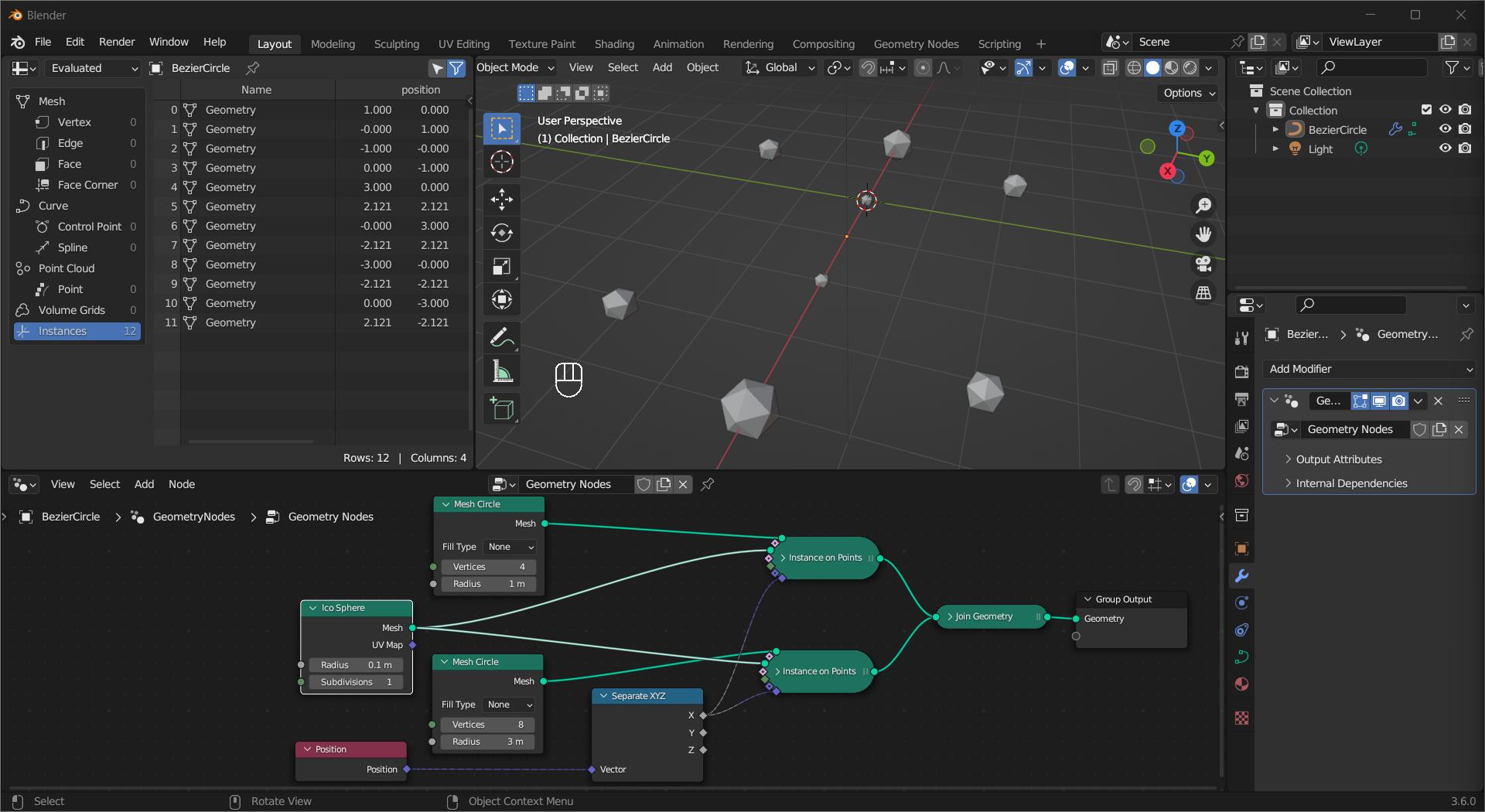
Field#
If you see a diamond socket on a node, you will know it is for a Field. A field is a function instead of a value, for example, the Edge Crease value of the Subdivision Surface node is retrieved from a Random Value node when evaluated. It is important to remember that because fields are functions, the same field linked to multiple nodes will not send the same data to them, just like calling a function multiple times with different parameters. In the following example, the size of the instances depends on their local X coordinates, you can see the X socket output different data for the two sets of points.
Tip
A field input socket that has a dot at the center indicates this input is currently using a single value.
Socket Colors#
The meaning of socket colors is consistent with shader nodes, with some notable additions:
Turquoise: Geometry(Mesh, Curve, Instances, etc.)
White: Collection
Salmon: Material
Light blue: String This also applies to fields.