Curve Modeling#
Though you probably can make everything just using mesh modeling, in some cases other tools can be more handy. For making pipes, ropes, or vector shapes, Curve modeling may save you a lot of trouble.
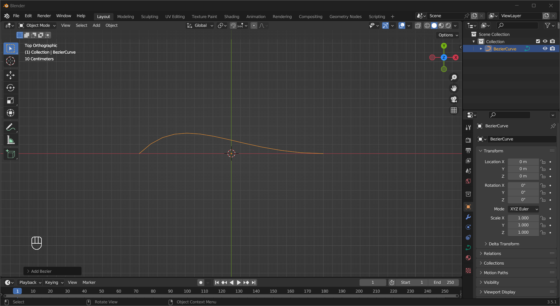
Add a Curve#
Adding a Curve is the same as adding any other object, press Shift + A or Left Mouse Click Add on the header to access the Add menu, then choose an object under Curve. Blender support two types of curves, Bezier and Non-Uniform Rational Basis Spline (NURBS), and we will focus on the former in this tutorial.
Curve Properties#
Unlike meshes, which are exactly what you see, curves are mathematical functions and what you see in the viewport is an approximation. If you want it to look smoother, switch the tab in the properties area to Object Data, then tweak the number in Shape > Resolution U.
Tip
For curves, U is the direction that goes along it.
By giving it a profile, curves are excellent tools to create cables, pipes, hoses, etc. In Geometry, adjust Bevel > Depth and Extrude to make a basic profile.
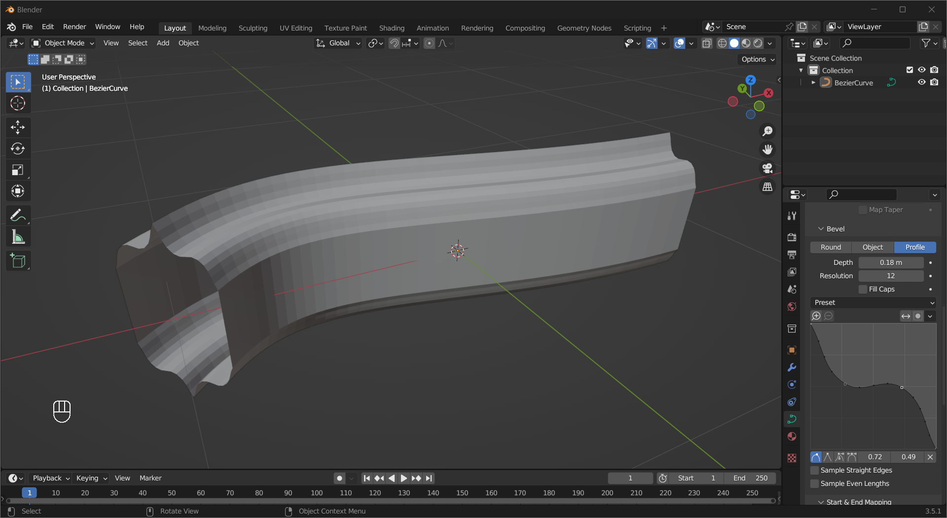
If you want to craft a more interesting profile, change the Bevel type to Profile, and tweak the graph.
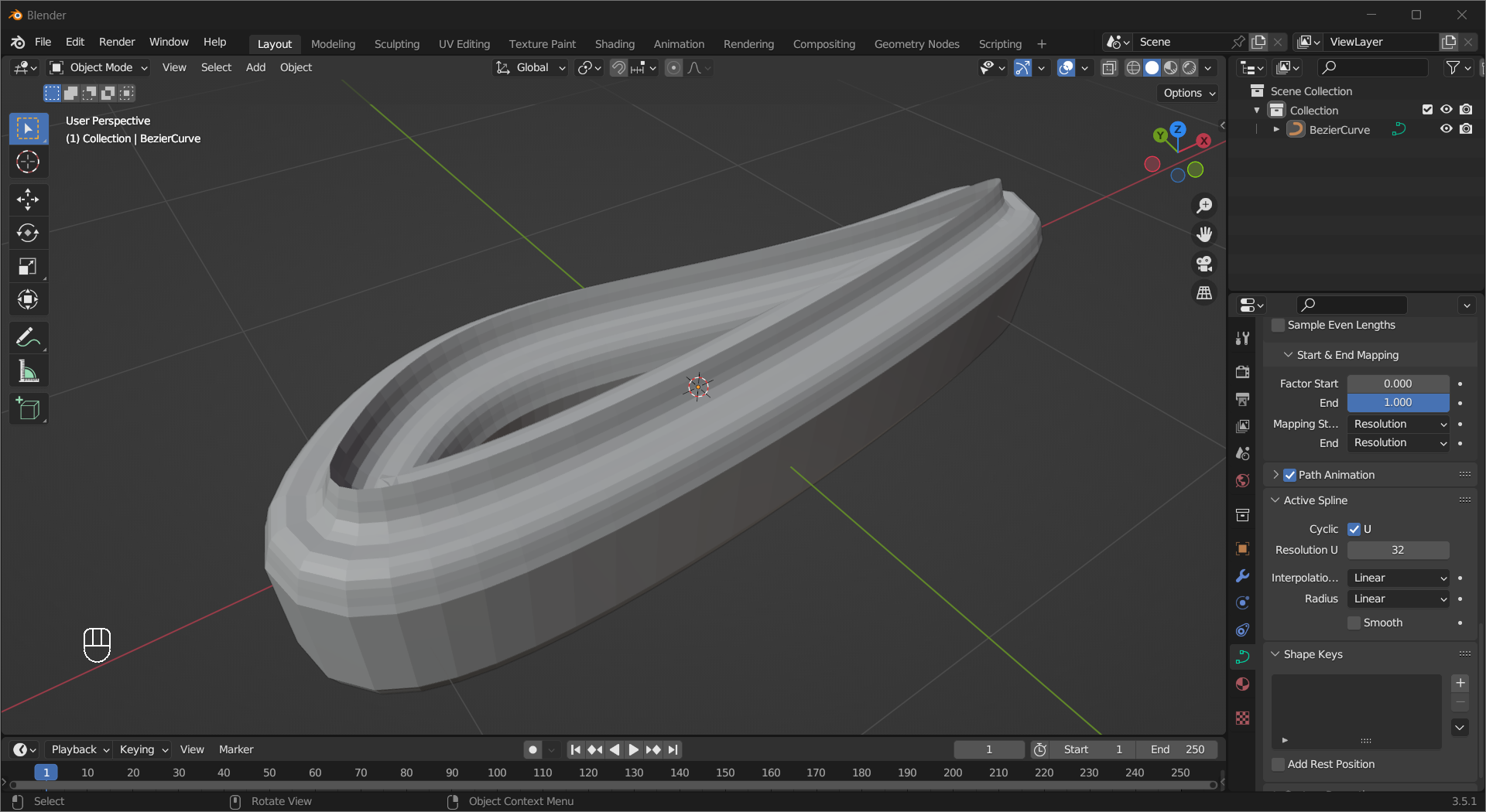
To make a loop, tick Active Spline > Cyclic U
Curve Editing#
Before you start editing, turn on Normals in Viewport Overlay menu by Left Mouse Click on the down arrow beside the Show Overlay toggle in edit mode.
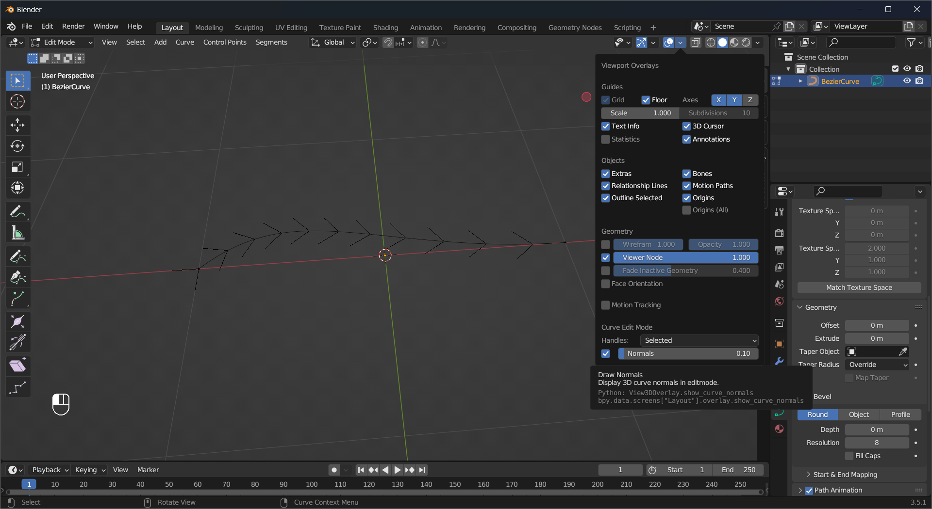
The added lines point to the direction in which the curve goes.
The little black squares on the curves are called Control Points. Like vertices, you can move them by pressing G and it will change the shape of the curve.
Handles are the pink lines that appear when you select control points, and every control point has a left handle and a right one. Moving the handles by selecting their endpoint and pressing G changes the shape of the curve, and both the angle and the length have effects.
You can also select the control point and rotate it by pressing R or scale it by S to change the rotation or length of the two handles at the same time.
Tip
All Move, Rotate, and Scale options from the previous sections are available, like locking on to an axis by pressing X, Y, or Z.
There are 4 different kinds of handles, and the default one is called Aligned, which keeps two sides always in a straight line as you have already seen. Select control points and press S or choose Control Points > Set Handle Type to change the type of the handles. The Automatic option will try to make the segments among the selected control points as smooth as possible; the Free type makes it possible to adjust two sides independently; Vector will make straight segments between control points.
Tilt is a property of a control point, it determines how the curve normals twist at the point.
It affects the profile of a curve with non-zero depth.
Radius controls the width/diameter of the curve extrusion/profile at a control point.
The Extrude tool works for curves too. Select a control point and press E or choose Control Points > Extrude Curve and Move to create a new control point and adjust its position.
To add new controls point between existing ones, select the control points and Right Mouse Click then choose Subdivide. The existing handles will be adjusted to keep the current shape of the curve.
A Segment is part of a curve between two control points. To create a segment between two control points, select the two points and press F (Similar to Fill in mesh editing) or choose Control Points > Make Segment on the header.