Physically Based Rendering (PBR)#
Physically Based Rendering (PBR) is an approach that aims at making your 3D object looks more realistic. Actually, The Principled BSDF is a PBR shader, so you have already used it in the last section. Here we will see how to make it better.
Shader Nodes#
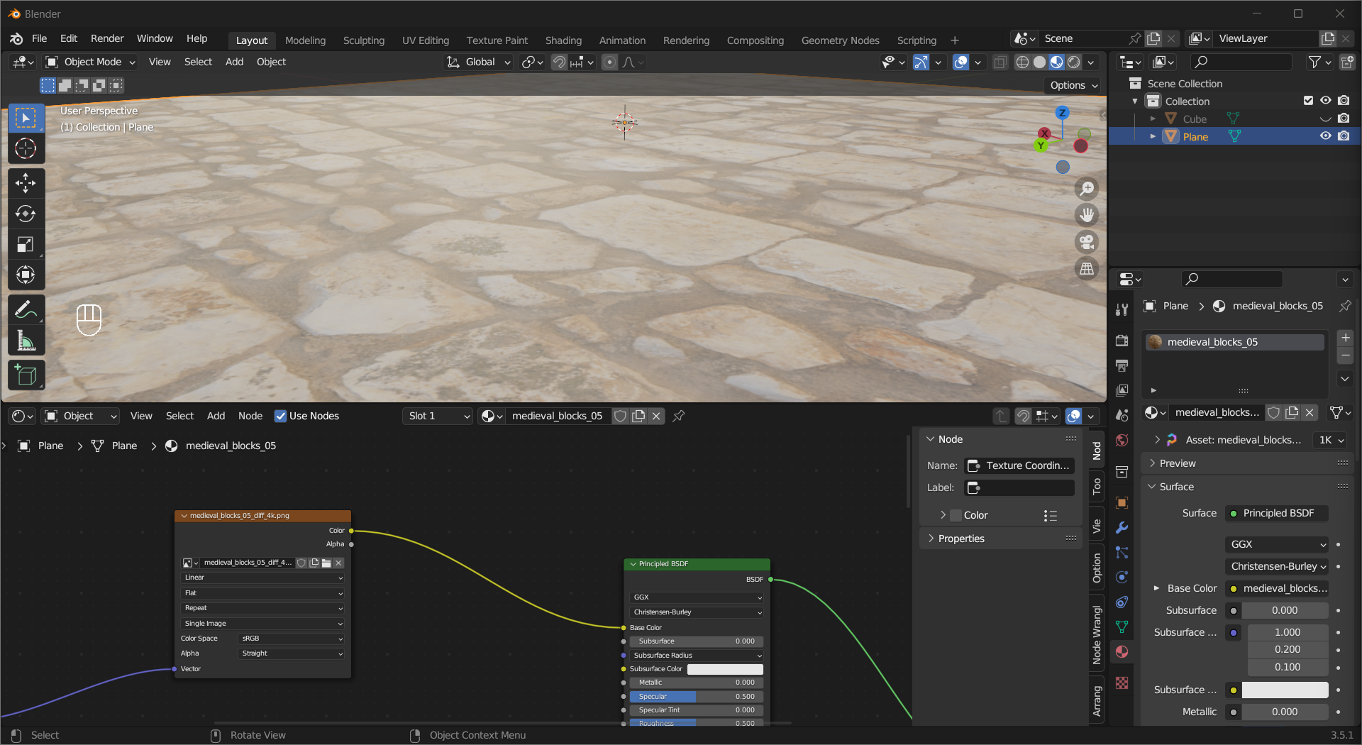
As we learned in the last section, materials are made of shaders. To make realistic materials in Blender, we will need to combine principled BSDF shader with other Shader Nodes to create a Node Tree. If you have a PBR material, switch one of your areas to Shader Editor and you will probably see something like this:
Tip
There are a lot of free/paid PBR materials available online. The one shown here is obtained from Poly Haven.
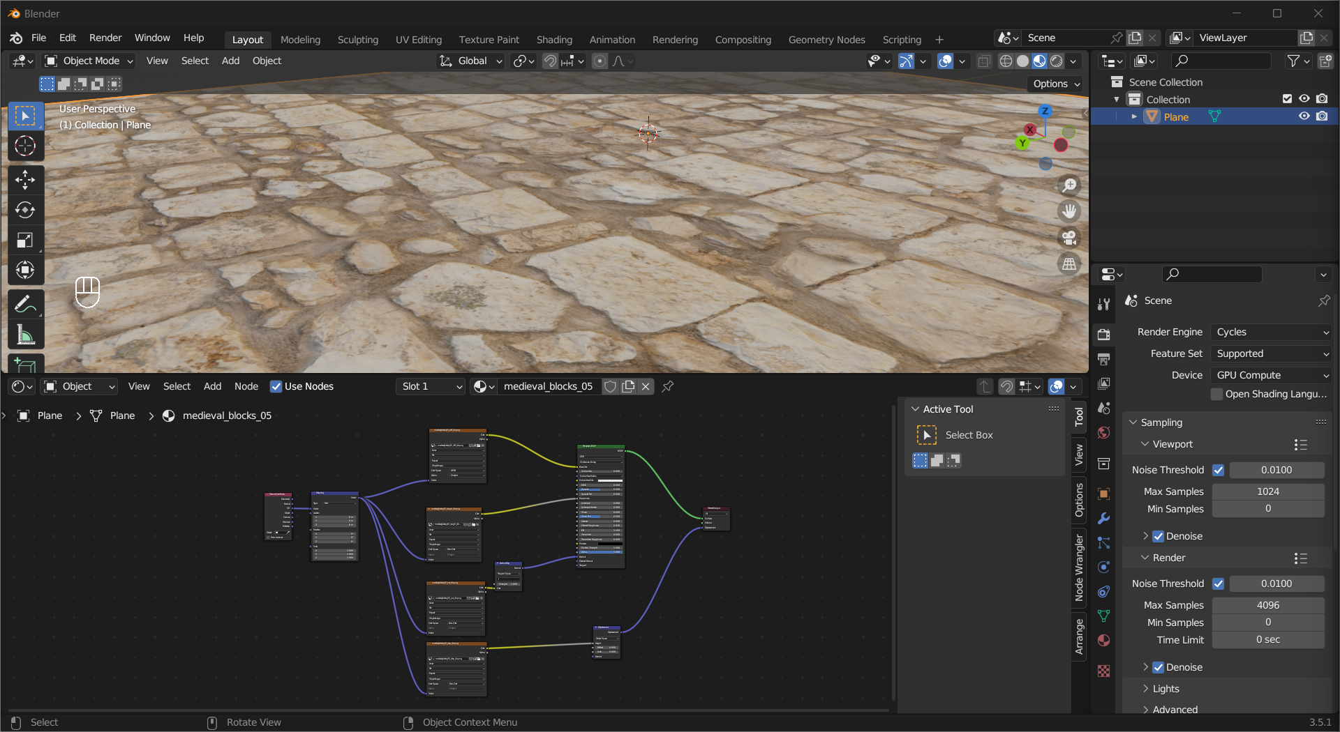
The rectangles are the nodes, you can think of them as functions with inputs and outputs, and the squiggly lines connecting them are called noodles (yes, it is official). The noodles go from the outputs of nodes to the inputs of other nodes, representing the connection among them. To add a node, press Shift + A or Left Mouse Click Add to bring up the Add menu, then choose the node you want to add. If you know the name of the node, you can use Search... in the menu. To link two nodes, hold Left Mouse Button on a Socket, then drag it to another. When you want to unlink, hold Ctrl + Right Mouse Button to cut the noodles.
Tip
You can collapse a node by Left Mouse Click on its top left to make the UI look cleaner.
Now, let’s look into the components of a PBR material.
Texture Coordinate and UV Mapping#
The Texture Coordinate node defines how the textures should be put on the object and the Mapping node allows you to make adjustments to the placement and scale.
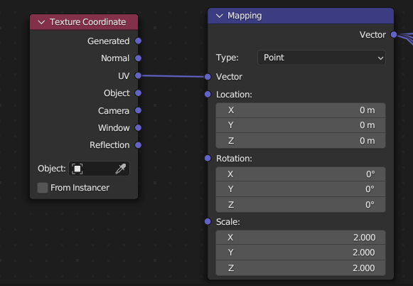
A common choice is UV, which means using a UV Map. UV Mapping is a process of mapping the surface of a mesh to a 2D space so a 2D texture can be applied. In Blender, Suzanne (the monkey) comes with a pre-made UV Map, and you can adjust it in the UV Editor area:
Tip
“U” and “V” are the “X” and “Y” of a different coordinate system.
The choice of seams has a major impact on the end result
To make a UV map manually, first you need to tell Blender where should the surface spit by selecting the edges then Right Mouse Click and choosing Mark Seam. Select the faces to be included in the new UV map and press U or Left Mouse Click UV on the header to open the UV Mapping menu, then choose Unwrap.
Besides UV, Generated gives you coordinates automatically generated from mesh, and Object lets you control the coordinates with an object.
Texture#
A texture allows different parts of the mesh to have different colors. Add an Image Texture node, load an image from a file and connect the Color output to the Base Color input socket of the Principled BSDF shader. The object will have texture on its surface, but still looks rather flat, like in early 3D video games.
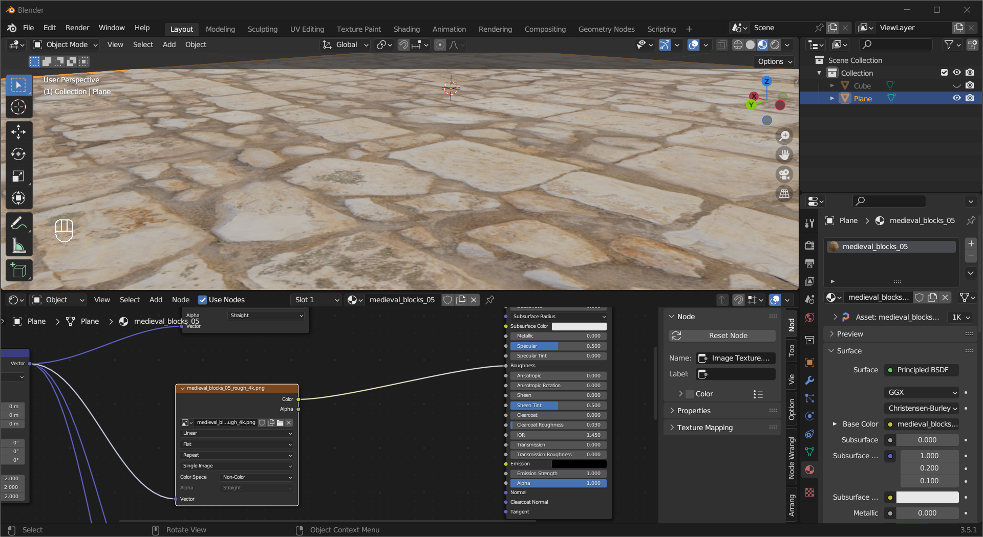
Roughness Map#
One way to make the material look better is to make it have some rough spots. The Roughness Map is a grayscale image when plugged into a Roughness socket, lighter-colored parts will have higher roughness values, darker ones with lower values. Similar to adding texture, load the roughness map in an Image Texture node, change the Color Space to Non-Color, then link Color to Roughness. Compared to the previous image, you can see the material now has more depth to it.
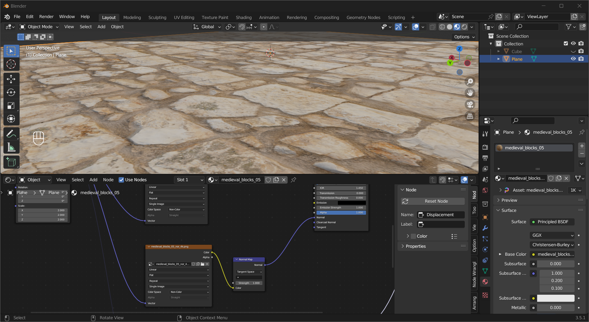
Normal Map#
In the last chapter, we used Shade Smooth to manipulate the normals on the pixel level and made objects look smoother than they actually are. The Normal Map functions in a similar way, but instead of making the surfaces look smooth, it can make them look more detailed. The image that stores the normal map has its R/G/B channel representing the X/Y/Z (the order may differ) part of the normal vector. To add it to the material, make a new Image Texture node and load the map, change the Color Space to Non-Color, then link Color to a Normal Map node, finally connect the output Normal socket to Principled BSDF shader’s input Normal socket.
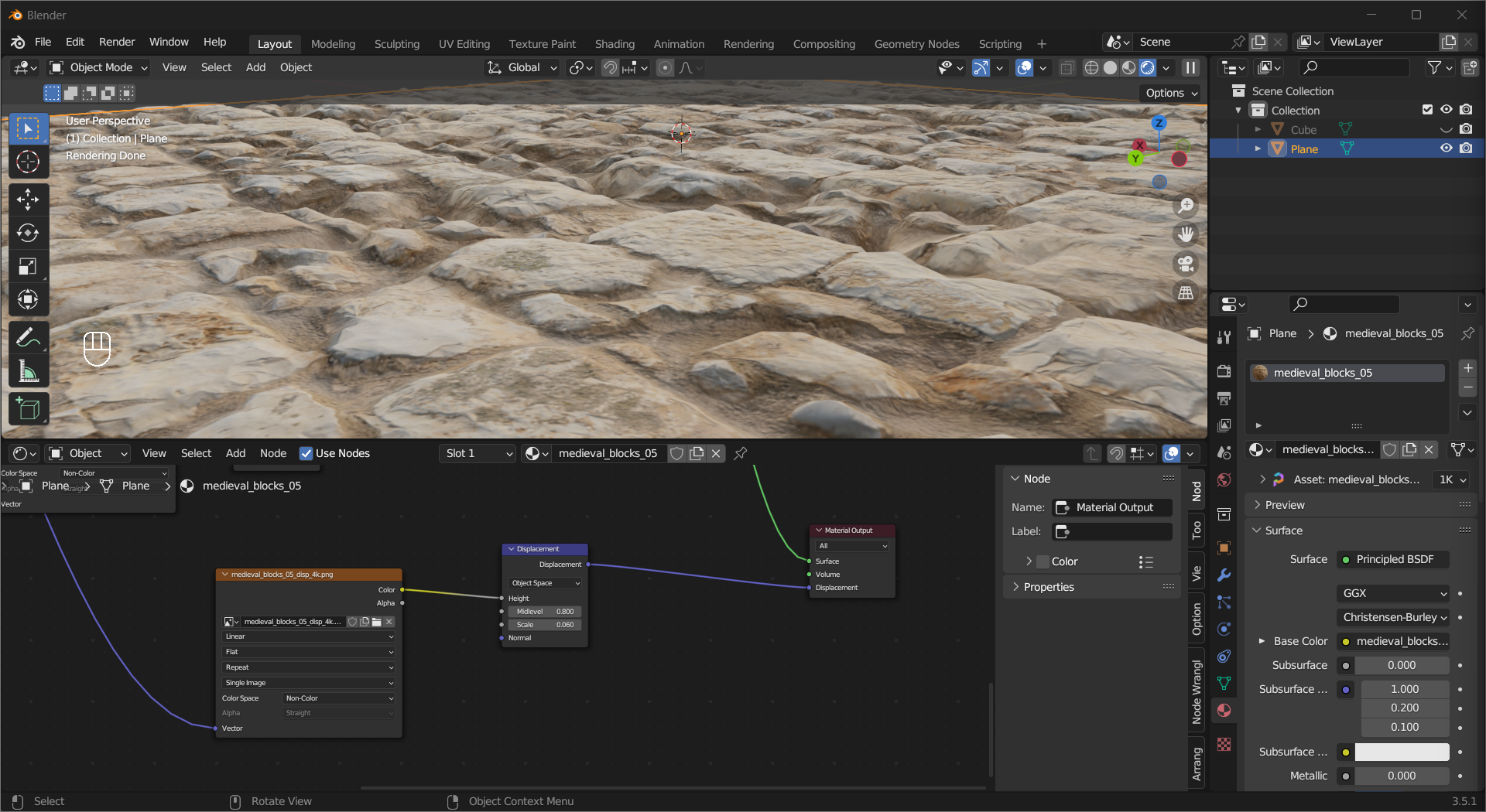
Displacement Map (Cycles only)#
If you think the normal map is adding “fake” detail, then the Displacement Map is the real deal. A displacement map stores the height information of the material, and it deforms the mesh at render time. To add Displacement, load the map in an Image Texture node, change the Color Space to Non-Color, then plug the Color output into the Height input of a Displacement node, and connect its Displacement output to the Displacement input of the Material Output node. To see the effect, you need to make sure Settings > Surface > Displacement in Material property tab is set to Displacement only or Displacement and Bump. Due to the high computational cost, this technique does not see much usage in real-time rendering.
Tip
The effectiveness of roughness map, normal map, and displacement map differ vastly among different materials.
Tip
Adaptive subdivision give objects closer to the camera more subdivisions and far ones less.
For displacement to work properly, the mesh needs to have enough vertices. If not, you can use the Subdivide tool in edit mode, or add a Subdivide Surface modifier. An experimental feature called Adaptive Subdivision can also help with this issue. In Render properties, change Feature Set from Supported to Experimental, then in the Subdivide Surface modifier you will see a new option called Adaptive Subdivision, turn it on and you can see the effect. You can tweak it in Render(Properties) > Subdivision.