Mesh Modeling#
Mesh Modeling is the most common way to make 3D models for all kinds of things. Before we dive into how we do it, let’s go through some basics first.
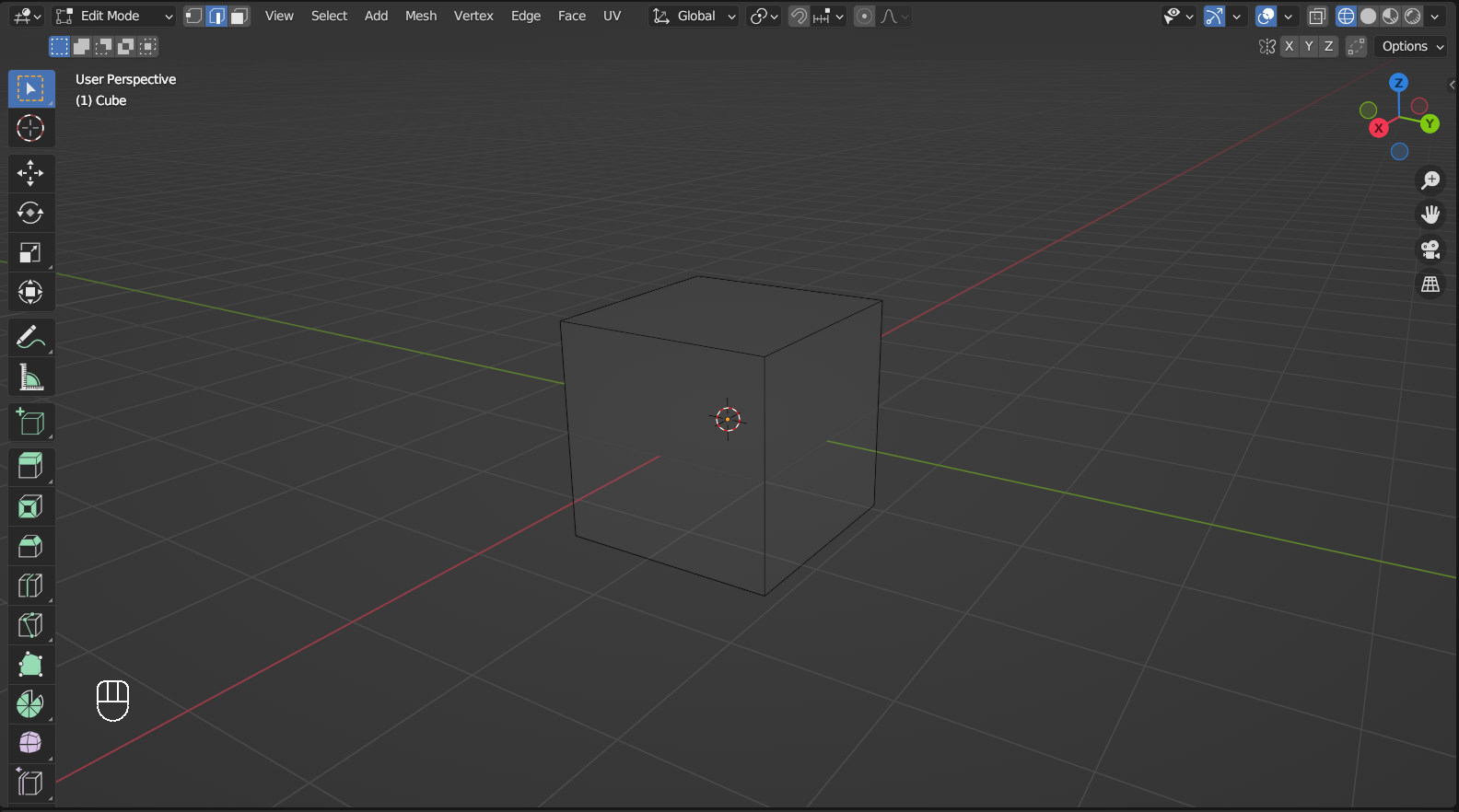
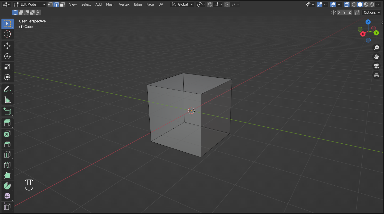
Edit Mode#
Edit mode is the 3D viewport interaction mode in which we do all the mesh modeling. Select a mesh object(like the cube you already have), use the drop-down menu on the left side of the header or press Tab to enter edit mode. You can also select multiple mesh objects to edit them at the same time. Once in edit mode, the toolbar offers a different list of tools, and the header also partially changes compared to object mode.

Vertex, Edge, and Face#
All mesh consists of Vertices, Edges, and Faces. Vertices, represented by small squares in Vertex Select mode, are points in space without any volume. Edges are lines created by connecting two Vertices, and faces are surfaces/polygons defined by the edges surrounding them. To modify vertices/edges/faces, you can switch to the desired Select Mode, by Left Mouse Click on their respective icons on the right of the object interactive mode selection, or pressing1,2, and 3(not to be confused with Numpad 1, Numpad 2, and Numpad 3)
Tip
If this is the first time you ever enter edit mode, The
Select Modeshould beVertex Select.When you switch the
Select Modefrom face select toEdge/Vertex Select, the edges/vertices associated with the chosen face will remain selected. This also applys to changing fromEdge SelecttoVertex Select.
An important property of a face is its Normal. If you still remember your math, the normal vector is the vector perpendicular to a surface, and this is also the case in 3D modeling. It is used to determine the direction a face is pointing and is crucial to shading.
Tip
If you just want know whether you are looking at the front or back side of the faces, open the
Viewport Overlaymenu and tickGeometry > Face Orientation. The front of a face will be blue and the back will be red.
This is Suzanne the Monkey, you can add her to your scene in
Add > Mesh > Monkey.
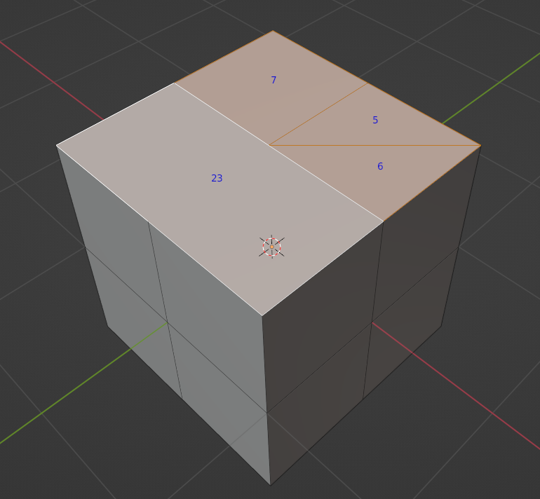
Tri, Quad, N-Gon, and Pole#
To make nice-looking meshes, there are some concepts you need to remember, and an important one is the type of faces you will be making. A face with 3 edges is called a Tri(triangle) (like face 5 and 6 in the image), 4 called a Quad(quadrilateral)(like face 7), and 5 or more an N-Gon (like face 23). Generally speaking, quads are considered the most desirable because they work well with all the tools in 3D modeling software; tris does not work with certain tools, like loop cut(you will see it soon); N-Gons should be avoided because they are prone to producing unwanted results.
Tip
To see the indices, you need to turn on Developer Extra in Edit > Preferences > Interface > Display, then open Viewport Overlay dropdown menu on the right side of the header (to the left of Viewport Shading toggles) and tick Developer > indices.
Tip
You can find out more about topology in 3D modeling here.
Another important concept is the Pole, which are vertices connected to three, five, or more edges. They may cause issues when subdividing or deforming the mesh. A pole with three edges is called an N-Pole
and one with five edges, usually formed as a result of extrusion, is called an E-Pole.
These two kinds of poles can form naturally and are not always possible to get rid of. On the other hand, poles with six or more edges should be avoided.
Viewport Shading#
To have a better look at the mesh you are working on, you may want to change the type of Viewport Shading. The default is the Solid Mode, which renders the mesh objects in grayscale and assumes the light comes from the point of view.

If you want to check the overall structure of the mesh, you can switch it to Wireframe Mode by pressing Z and choosing Wireframe or Left Mouse Click on the icon located on the right part of the header. In this mode, faces will not be shaded, allowing you to see vertices and edges more clearly.
Sometimes you need to see and select the vertices/edges/faces on the other side of the mesh, toggling on X-Ray by pressing Alt + Z or Left Mouse Click on its icon allows you to do that.
The other two views, Material Preview and Rendered, will be introduced in later chapters.
Mesh editing tools#
Basic selecting works the same as in object mode (see the last section for details), just make sure you are in the right select mode (vertex/edge/face). To make mesh editing easier, edit mode offers a lot more select tools, and you can find them in the Select menu on the header. Many of them are quite situational, but Select Loops is the one you are going to use all the time. Hold Alt and Left Mouse Click on an edge to select the whole edge loop, and it works in all 3 select modes.
Tip
Select Loops only select the well-defined part of a loop.
Select Random helps you make irregular shapes. Choose Select > Select Random to add random vertices/edges/faces to the selection, depending on the current Select Mode.
Tip
Check the Scale tab for the scaling operation in this example.
Tip
Check Move, Extrude, and Inset tabs for the other tools used in this example.
Checker Deselect is useful for creating interesting patterns. Select the vertices/edges/faces first, then choose Select > Checker Deselect to get the effect.
For more complex meshes, Select Linked is useful to get all connected parts. Move the cursor to the part of the mesh you want to select, then press L to select all connected vertices/edges/faces. Alternatively, select a vertex/edge/face, then choose Select > Select Linked > Linked.
Similar to moving objects, you can press G to move vertices/edges/faces in edit mode. Locking on axes and snapping are also available here.
One useful addition is called Edge Slide, and it allows you to move vertices along edges and edges along faces. To activate it, select the vertices or edges and press G twice. If you want to go beyond the limit of the edges/faces, press C to toggle Clamping.
Rotating edges and faces are the same as rotating an object, see the last section for details.
Scaling edges and faces are the same as rotating an object, see the last section for details.
Extrude is an essential tool for making interesting shapes. It works on vertices/edges/faces, and you can activate it by pressing E or Left Mouse Click its icon in the toolbar, then move the new vertices/edges/faces to the desired location. By default, extruded face moves along the normal but you can press Z to remove this restriction, otherwise locking the movement to axes works the same as the move tool. One quirk of the extrude tool is that unlike most other tools (move, rotate, scale, etc.), Right Mouse Click does not cancel the operation. Instead, the new vertices/edges/faces will be in the exact same place as the old one, and may cause problems down the line. A simple way to check whether there is a duplication is to select the vertices/edges/faces and try to move them a little. For the alternative extrusion modes, hold down Left Mouse Button on its icon on the toolbar or press Alt + E.
The Inset tool comes in handy when you want to create a smaller surface in an existing surface for extrusion or other purposes. Select a face then press I to inset it, move your cursor to adjust and Left Mouse Click to confirm or Right Mouse Click to cancel. You can also inset multiple faces simultaneously by selecting all of them, and if they are connected and you want to inset them separately, check Indivudial in the Inset Faces menu that appears on the bottom left.
Loop Cut is a useful tool to add new edges while keeping the flow of the geometry. Put the cursor to where you want to add the edge loop and press Ctrl + R or Edge > Loop Cut and Slide, then move the cursor toward the direction in which the edge loop goes. Scroll up to add more loops and down to subtract, Left Mouse Click to confirm and activate Edge Slide (check Move tag for the details). This tool does not work well with tris and N-Gons because the loop can not be defined.
You can also use it to cut a single edge or face.
The Knife tool allows you to add arbitrary edges (and vertices that come with them) to a mesh. Press K or Mesh > Knife Topology Tool to activate it and the cursor turns into a knife shape. Start a cut by Left Mouse Click, then move the cursor and Left Mouse Click again to draw a line, and you can keep repeating the process. Unlike most tools in Blender, Left Mouse Click does not cancel the operation, but it lets you make a new starting point. By default, the tool only cuts the visible part of the mesh (even when X-ray mode is on), press C to cut through the entire mesh to alter that behavior. Press Enter to confirm the cuts or Esc to cancel.
Tip
Holding Shift let you snap to the center of an edge.
The knife tool is powerful but you can easily create bad topology with it if you are not careful, try other options(like
Loop Cut) first.
No edge on real-life objects are as sharp as the default cube, and the Bevel tool allows you to make rounded edges. Select the edges you want to bevel, then press Ctrl + B or Edge > Bevel Edges to activate the tool. Drag the cursor to adjust the width and Scroll to increase or decrease the number of segments, then Left Mouse Click to confirm or Right Mouse Click to cancel.
The Subdivide tool gives you more polygons to work with. Select the faces you want to divide, then Right Mouse Click and choose Subdivide.
Select the vertices/edges/faces to delete and press X to bring up the Delete menu, then choose to Delete/Dissolve them. Deleting vertices/edges will also delete the edges/faces which are dependent on them; dissolving will try to keep the geometry intact.
Select the vertices to merge and press M to bring up the Merge menu, then choose an option to decide where the merged vertex should be.
The Rip tool makes copies of selected vertices/edges and creates a hole in the geometry, press V or choose the Rip Region tool in the toolbar to activate it.
Tip
The vertices/edges selected after ripping depends on the position of your cursor.
The Fill tool let you connect vertices to make new edges or faces. For the former, select two vertices and press F; for the latter, select 3 or more vertices (2 or more edges work too) then press F.
If the new face you are trying to create is going to be an N-Gon, Grid Fill can help you avoid that. select the edges (This tool only works on a closed edge loop or a pair of opposite edge loops) and press Ctrl + F or Left Mouse Click Face on the header to bring up the face menu, then choose Grid Fill.
Reusing part of an existing object can save you a lot of time. Select a part of a mesh (copy it first if you still need it in the original) and press P or choose Mesh > Separate on the header to bring up the Separate menu, then select Selection.
Proportional Editing is not a mesh editing tool by itself, but tuning it on allows Move/Rotate/Scale tool to influence adjacent vertices/edges/faces. Press O or Left Mouse Click
It is especially helpful if you need to edit high poly mesh.
Check the end of this chapter to see how these essential tools are used in mesh modeling.
Tips#
Tip
Use Proportional Editing may help if you need to edit High poly mesh.
Always start with low poly mesh. High poly mesh is harder to work with, and it is much easier to turn low poly mesh into high poly ones (e.g. adding Subdivide Surface modifier) than the opposite.
Topology refers to the distribution of vertices, edges, and faces in 3d modeling, and how to keep it clean is an important but complicated topic. For beginners, following these points would be a good start:
Avoid N-Gon, and try to use quad as much as possible
Keep mesh density even
Keep an eye on duplicated vertices, edges, and faces, especially when extruding
Make sure normals are pointing right directions
It definitely helps to make your 3D model look right if you have reference pictures. To add a reference image to the viewport, drag the file into the viewport or press Shift + A and choose Image > Reference and find the file in the browser. Adjust the location and rotation of the references for the three views so they line up, then Left Mouse Click on the cursor icon in the outliner for the reference objects to disable selection so you will not accidentally select them during modeling. Finally, you can make them only visible in the front, side, and top views, by unchecking Object Data Properties > Empty > Show In Perspective
Tip
If the cursor icon for disabling selection is not there, Left Mouse Click on the funnel icon on the header of the outliner area, and turn it on under Restriction Toggles.