More about Geometry Node#
The Add menu in the geometry node editor looks much more crowded than the shader node one, but you do not have to know all the nodes to start using it. In this section, we will go through some of the most used nodes.
Keyframe and Driver#
The values in the input sockets of the nodes can be keyframed like any other properties, and adding drivers is also possible.
More Nodes#
For Texture, Group, Layout, and most of the Utilities nodes, check shader nodes.
The Capture Attribute node can save field outputs for later use. In this example, the node saves the postion of the corners of the cube, and by subtracting the current position of the instances, we can get the vector to rotate the cones to always point at the corners.
Tip
The difference between two locations gives a vector pointing from one to the other.
The Store Named Attribute node is very similar to the Capture Attribute node, the difference is you need a Named Attribute node when you read the stored attribute.
Nodes here are similar to the Value node in shader nodes but comes in different types. Use them as an input to control different input at the same time.
You can find the Group Input node here if the default one is deleted.
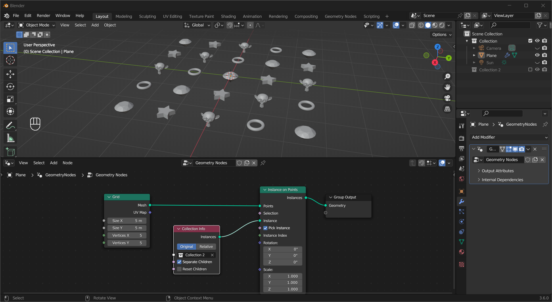
If you want to put instances of a series of different object on points, you can put them in a collection and bring the whole collection in using Collection Info. Ticking Separate Children in this node and Pick Instance in the Instance on Points node will give you the effect in the example.
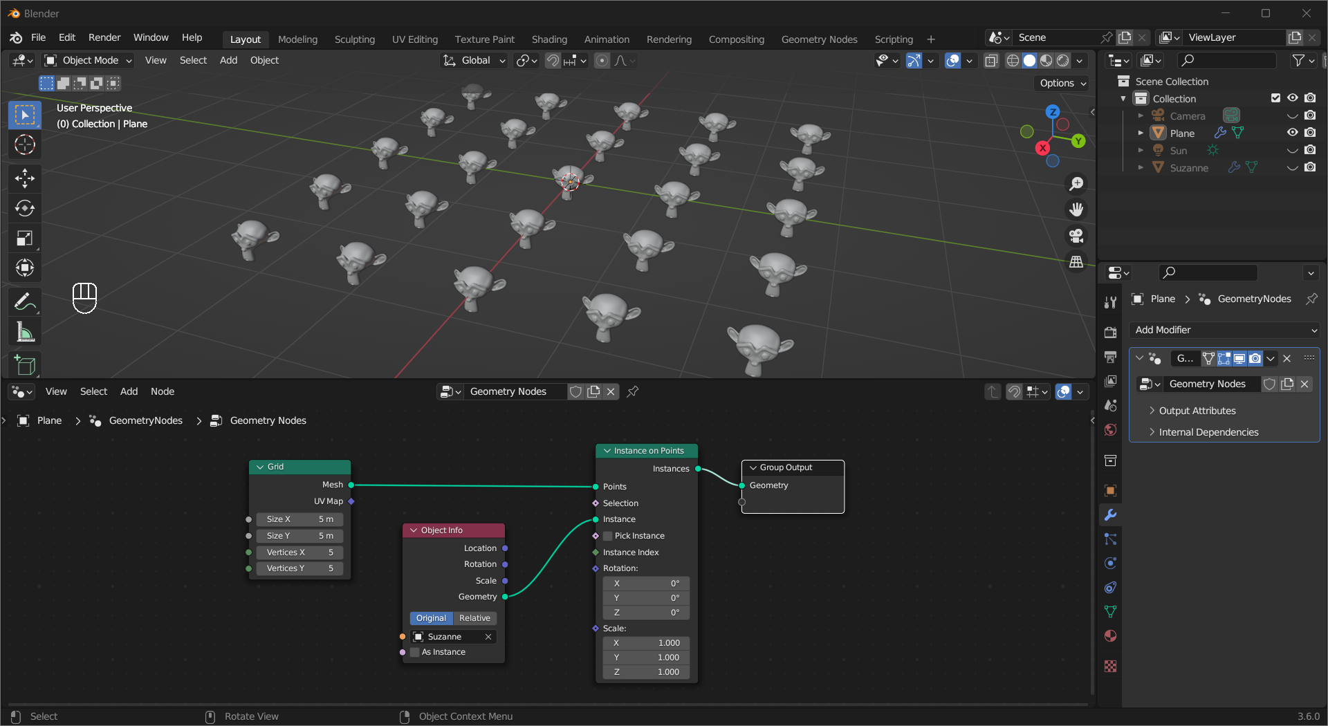
The Object Info node allows you to bring an object into the node tree.
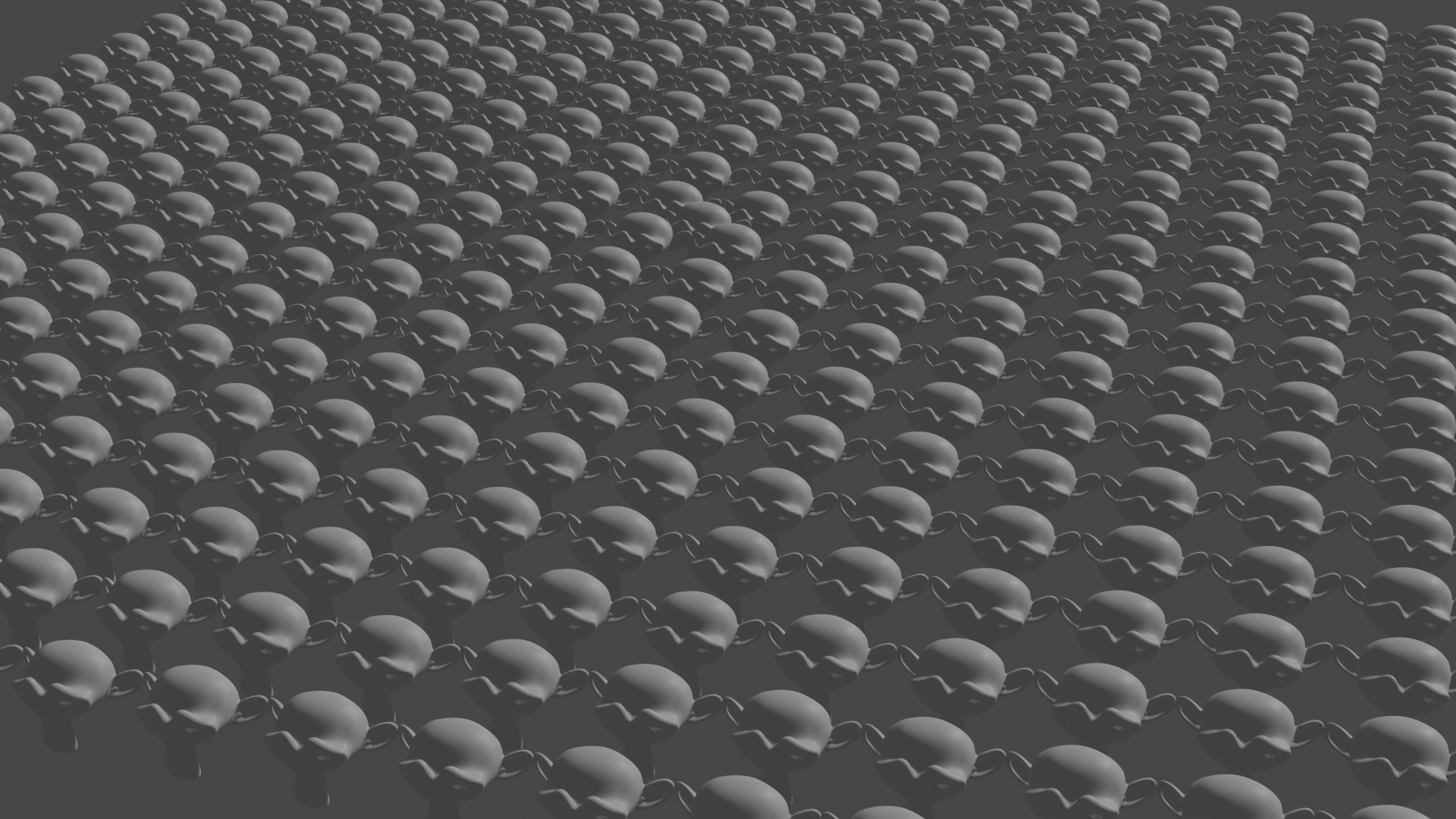
When you are working with a lot of meshes in a scene, like foliage, the 3D viewport can get irresposive due to high polygon count. The Is Viewport node along with a Switch node allows you to replace the actual object with low-poly proxies in the viewport.
In viewport:
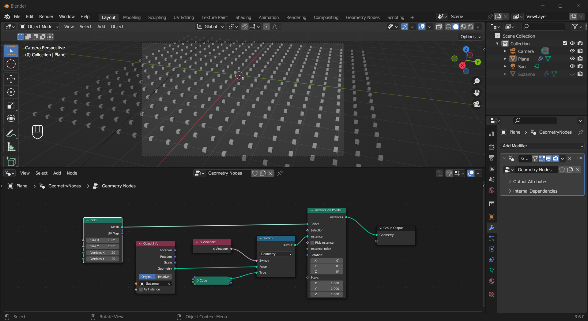
Render:
If you accidentally deleted Group Output you can find it here.
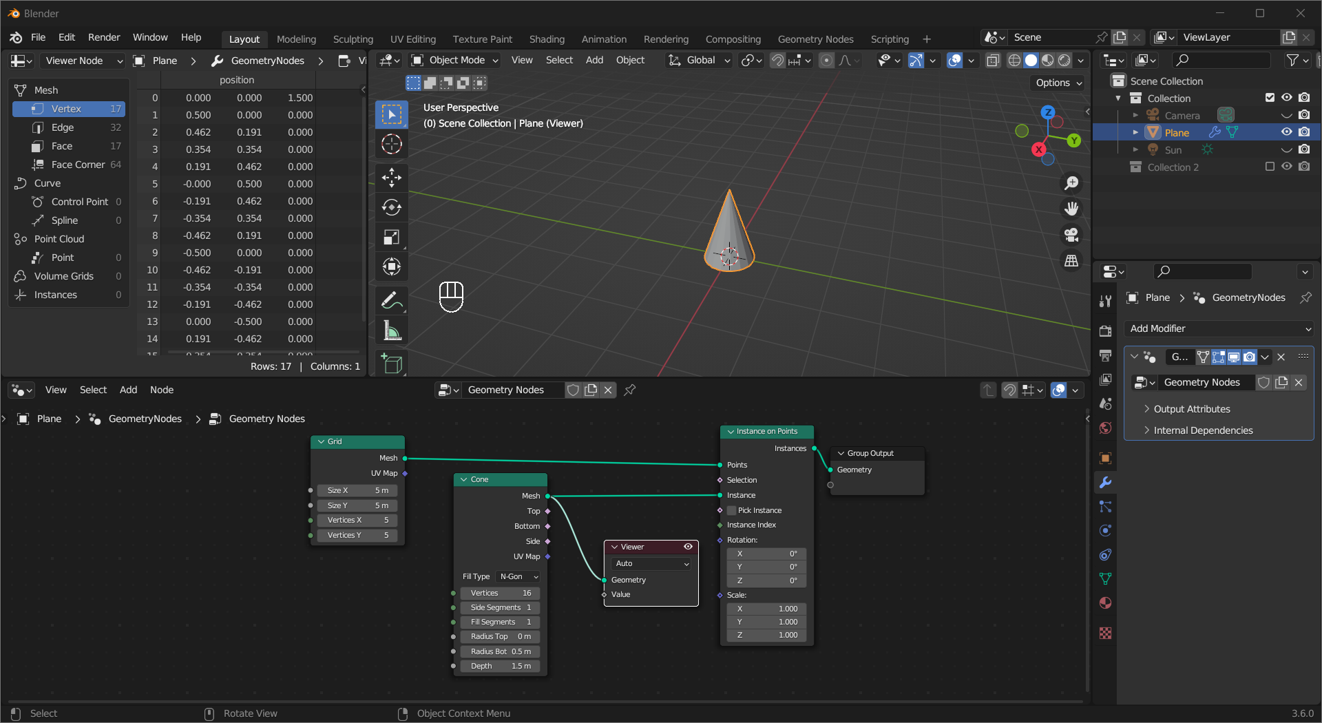
The Viewer node allows you to check data and geometry inside a node tree. Ctrl + Shift + Left Mouse Click on a node to connect it to a Viewer node.
Nodes here provide fields for retrieving geometry infomation, you can find them in examples for other nodes and the projects at the end of the chapter.
The Geometry Proximity node calculates the closest distance to the target geometry or the closest location on the target to the surface. In this example, the density of the points on the surface is controlled by the distance to the cube object.
The Raycast node projects the source object onto the target. Ray Direction controls the direction of the projection and Ray Length restricts the maximum distance of this effect, and the node can output how the target is “hit”. This example shows how you can move cubes in a grid with this node.
The Set Position node can change the position of points/vertices/control points. You can filter the points you want to move using the Selection input, set their new position in Position, or move them based on vectors with “Offset”. See how this node works in examples for nodes like Capture Attribute, Raycast, etc.
The Transform Geometry node changes the position of the location, rotation, and scale of the input geometry, similar to the Item > Transform menu in the sidebar of the viewport. See its usage in the projects section at the end of this chapter.
A Bounding Box is the minimum box mesh that encapsulates a geometry, and the Bounding Box node creates one for the input geomery. The Bounding Box socket gives the box mesh, and the Min and Max sockets outputs the -X/-Y/-Z and +X/+Y/+Z location of the box respectively.
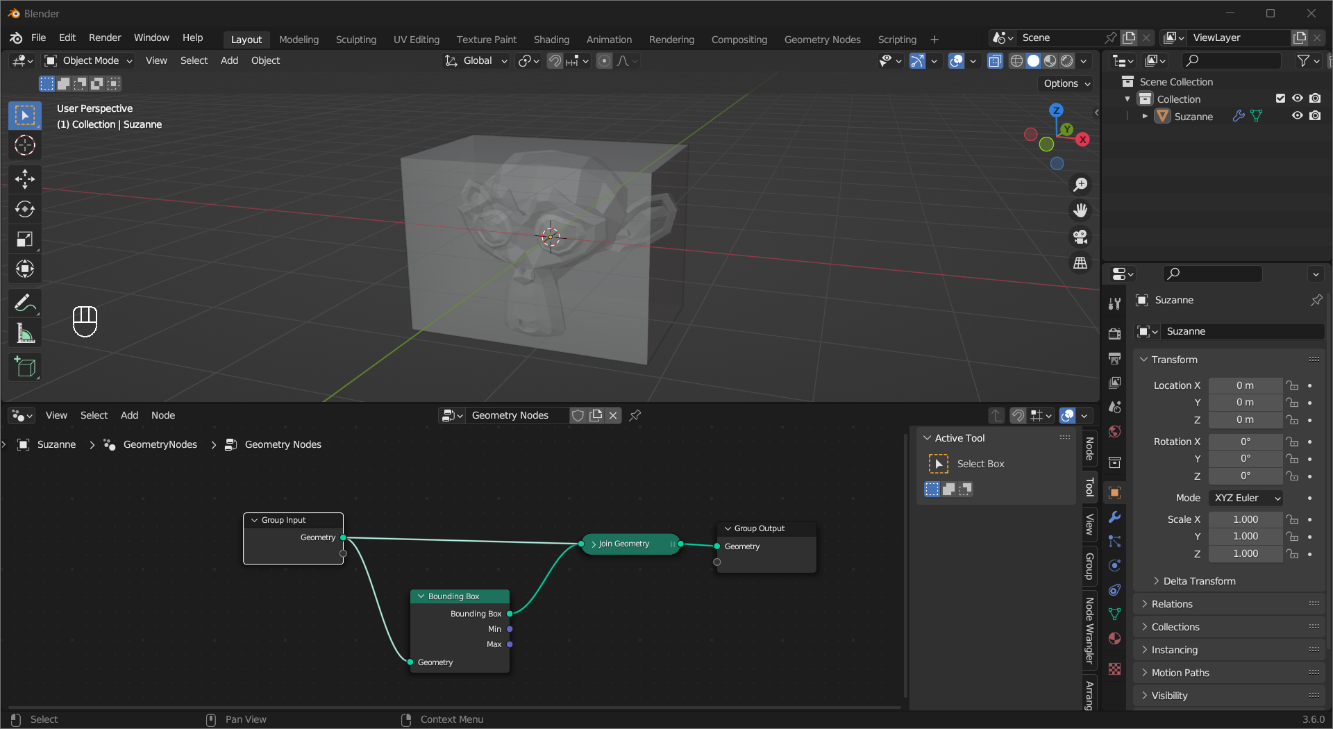
The Join Geometry node can take any number of geometry inputs and merge them into one. With Node Wrangler enabled, hold Ctrl + Shift + Right Mouse Button on a node with geometry output then drag it onto anther one will create this node with these two nodes linked to it.
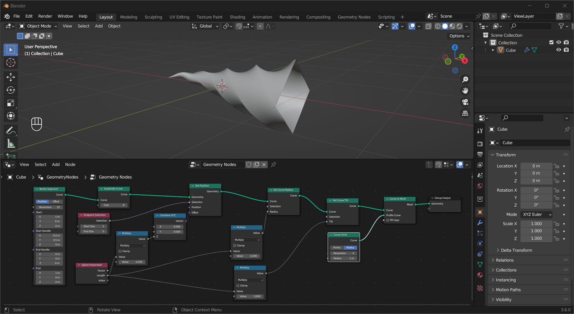
Nodes in this submenu can help you make new curves, modify curves, or read curve-related data. In this example, the Primitive nodes (like Bezier Segment, Curve Circle) make their respective curves, the Read nodes (like Endpoint Selection, Spline Parameter) retrieve information from the Bezier curve, the Write nodes(Subdivide Curve, Set Curve Radius, Set Curve Tilt, ) modify the curve, and Curve to Mesh, one of the Operation nodes, turn the curve into a mesh with a profile.
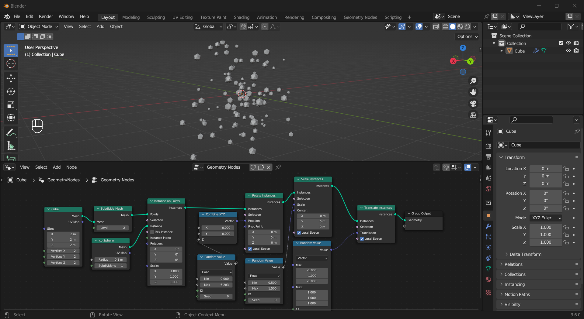
Apart from the Instance on Points node we have been using, nodes here can move/rotate/scale instances.
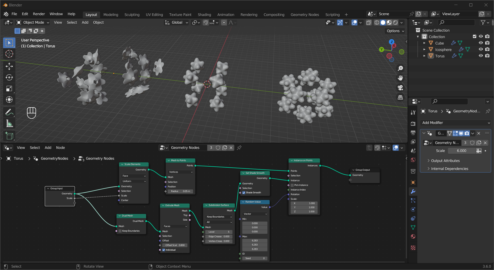
Although not as versatile as the manual mesh editing tools, the nodes in the Mesh submenu are powerful in their own ways. In this example, the same node tree is applied to 3 different meshes creating different results. The Dual Mesh node converts faces to vertices and vertices to faces, other nodes are self-explanatory.
Tip
Remember the geometry node group acts like a node group, you can add input and output sockets to it.
Another notable one is the Mesh to Volume node, combined with the Distribute Points in Volume node, you can generate points inside a geometry. In this example, the cones are placed randomly inside the source object (a cube) and pointing at the empty object.
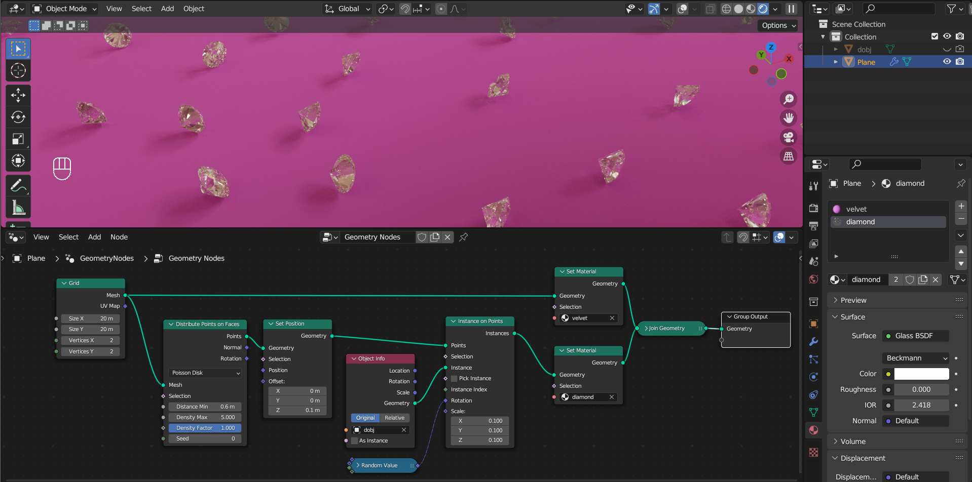
You can assign different material to different parts of the geometry using Set Material node.
Tip
You can choose any material in the data.
The Align Euler to Vector node allows you to align geometry with the direction of a vector. See the examples for the Capture Attribute and Mesh to Volumn node.
The Random Value node can help you create some variaty by generating random value of different types. Check examples for other nodes to see this node in action.
The Simulation Zone allows you to create custom physics effects by enabling one frame to influence the next. In this example, the Set Position node moves the points in a random direction every frame, and the random seed is changed per frame too.